N Gauge - Newcastle Emlyn****
Posted

Full Member
The front panel to the Llandyfriog Junction "Box" is now hinged and in place, holes for the bi-colour LEDs drilled and the temporary track layout plan sticky taped on the panel to test the fit.
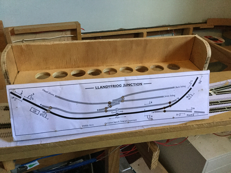
…and showing the panel down ready for wiring to commence…
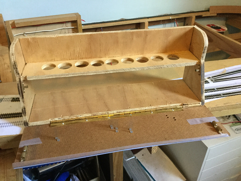
Some of the LEDs are in their holes but a further 4 are required to complete the panel.
Got my head back into my electronics book trying to work out just how to set up the resistors to balance the applied voltage. I guess because I don't do it all the time, every time I do this stuff I have to go back to the book to try and get current, volts and resistance sorted out in my head.
Nothing has blown up yet… But there is still plenty of time.
Marty

Posted

Full Member
Always try to look on the bright side of life!
Barney
Barney
Posted
Full Member
Marty
Posted
Guest user
 watching with interest mate
 Cheers
Matt
Posted

Inactive Member
Nice work on the schematic…….that`s brilliant and well suited to your railway.
I wait with eager anticipation to see where it goes from here.
:thumbs:thumbs:thumbs:thumbs
:cheers Gormo
"Anyone who claims to have never made a mistake, never made anything!!"
https://sites.google.com/site/greatchesterfordmodelrailway/home
https://sites.google.com/site/greatchesterfordmodelrailway/home
Posted
Full Member

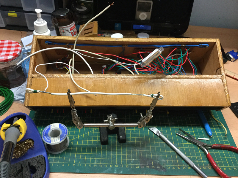
Test done with alligator clip test cables, now to wire 12 LEDs (each with 3 connections), 24 resistors (25 actually with the 1.2k voltage dropper in the line), 6 common returns, 18 relay connections and 6 x 12V ancillary power bus connections.
I'll be back in a while…
Marty
Posted
Inactive Member
Now the tedious bit…..wiring the lot up……but the finished product will be worth it. :thumbs
:cheers Gormo
"Anyone who claims to have never made a mistake, never made anything!!"
https://sites.google.com/site/greatchesterfordmodelrailway/home
https://sites.google.com/site/greatchesterfordmodelrailway/home
Posted
Full Member
… The first points indicators are predominantly complete, just need that connection to the board, and work on number two is 80% there…. And no burnt pinkies yet!
Cheers
Marty
Posted
Full Member
Underside of the plank looks like this…
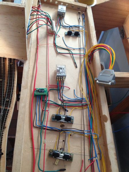
On the signal box panel all of the planks LEDs are wired up and tested (which did require a bit of head scratching and eventually a subsequent small rewiring when it didn't do what it was supposed to do!) and now it needs the levers.
In my case the majority of the levers are PECO single pole double throw passing contact levers for point actuation as shown earlier.
Also, as shown earlier the junction plan calls for 24 of the blighters! PECO make a plastic mounting box for 6 levers but putting 4 boxes side by side takes up more real estate than I am prepared to lose.
The Henllan lever frame was improvised from an old baking tray and apart from being a bit too thin and having too long a slot cut in it for the levers (there is a bit of unwanted flex) it works very well.
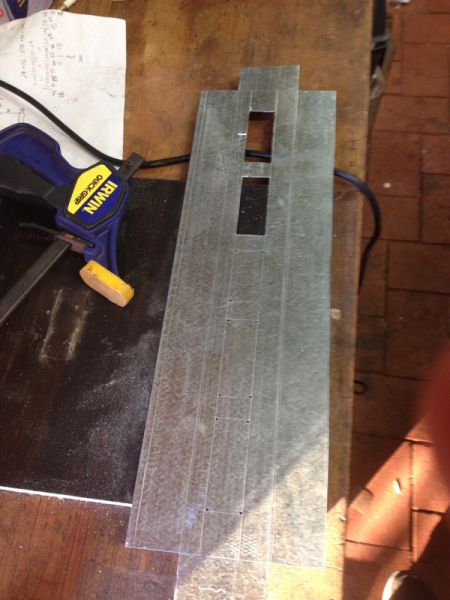
The option was to find a similar baking tray of 400mm length ( which we did manage to do in the local supermarket) or by a small sheet of 1mm galvanised plate and manufacture my own frame.
Since the galvanised plate was a better thickness and something new to try, a shiny bit of plate was purchased from the local mega hardware.
A basic design was sketched out on a bit of scrap paper and marking up and cutting began.
Here's the basic flat packed shape. You can see the scribed lines on the galv and the reciprocating multi-tool with the tungsten metal cutting blade ready for use.
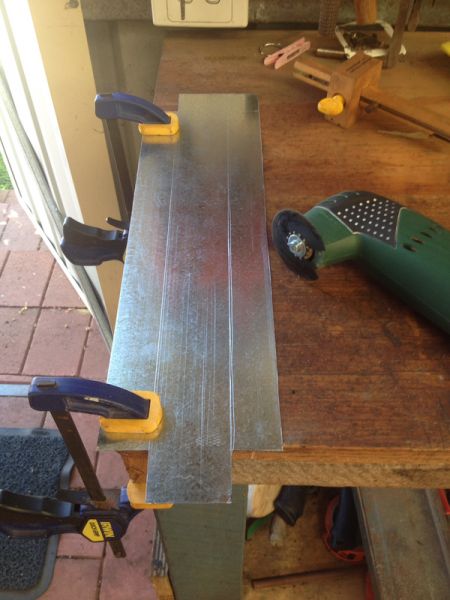
It's all cut freehand but the width of the cutting disc helps keep them straight. Then on to cutting out the slots for the lever switches by pre-drilling in the corners and then again carefully cutting with the multi-tool.
Two slots done, three to go…
And finally, this has taken weeks for me grabbing 30mins in the shed here and half an hour there, cutting a shallow groove on the reverse side of the bend line and bending the sides over an off cut of planking in the vice.
Eventually, there was a bit of grumbling about Bodgit and Scarper having to take it back to the workshop when it was about 2mm too long to fit into the signal box, it fits.
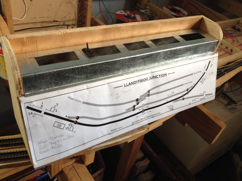
Next some staining and varnish on the box and some paint on the new lever frame… Oh, and wiring up the levers to the 25 pin D connector.
More as it happens….
Marty
Posted
Guest user
:thumbs
Posted
Full Member
Posted
Guest user
Not sure if it would work Marty but willing a solution for you.
it looks very tidy otherwise. Spot in.Cheers
Toto
Posted
Guest user
Posted
Full Member
Actually. I'm quite happy with the first one, it does the job, looks OK and being the first attemp I'm emotionally attached to it :lol:
Once I've bogged up the over cut on the new one it'll do fine. I'd thought of solder and a shim of plasticard epoxied in place and automotive patching bog… Whichever I think easiest at the time I reckon.
Marty
 Last edit: by Marty
Posted
Inactive Member
Any tidy up is only details …….don`t worry about it. I have no doubt that it`s impressive to anyone viewing it.
Once you`ve painted and varnished it, it will look a million bucks.:thumbs:thumbs:thumbs:thumbs
:cheers Gormo
"Anyone who claims to have never made a mistake, never made anything!!"
https://sites.google.com/site/greatchesterfordmodelrailway/home
https://sites.google.com/site/greatchesterfordmodelrailway/home
Posted
Full Member
Marty
Posted
Inactive Member
You gotta do what you gotta do!!!!…….I used to work for Bunnings actually. They would come in handy for me now, because they were always chucking out useful bits that could be used for model railways…..Oh well too late….I retired.?
:cheers Gormo
"Anyone who claims to have never made a mistake, never made anything!!"
https://sites.google.com/site/greatchesterfordmodelrailway/home
https://sites.google.com/site/greatchesterfordmodelrailway/home
Posted
Full Member
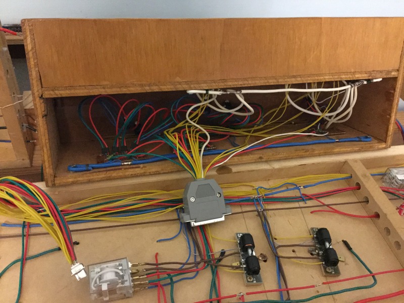
The back of the the junction box control panel looks like this…
:lol::lol: We've all been there right?! It will be worth it in the end.
The last couple of days has also seen Peco micro switch shenanigans on the only point for Llandyfriog junction that is a legacy from the old track alignment.
This point had to be lifted, adapted to allow frog polarity switching and relaid. Twice…. The continuity wires between the switch and stock rails were missed in the first go, luckily it was tested electrically before fixing down and their absence was discovered!
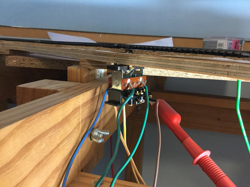
Once added the micro switch was a tricky little brighter to adjust, especially while under the base board, note to self, avoid anything that requires working under the baseboard!
Eventually, with Tracy's help, it worked and the relay has now been wired up and tested successfully. Just the LED indicator wiring back to the control panel to do, once the Peco PL 26 passing contact switches have been wired up.
Brother… On the up side… My soldering has improved.
Marty
Posted
Inactive Member
That`s tricky stuff to get sorted. It looks like you don`t have a lot of room there to work in either.????
I don`t like working under the boards and having to do all sorts upside down, so I can sympathize with you on that one.
:thumbs:thumbs:thumbs:thumbs
:cheers Gormo
"Anyone who claims to have never made a mistake, never made anything!!"
https://sites.google.com/site/greatchesterfordmodelrailway/home
https://sites.google.com/site/greatchesterfordmodelrailway/home
Posted
Full Member
Steady work with some help from my second son has got all of the wiring for the point motors and LEDs in the signal box panel sorted. What still needs to be done is the wiring for the signals , but that is going to be a slow process and I'm keen to replace the old Teifi siding and get trains running.
A 25 pin plug is wired up for connection between the panel and the plank. There will be a second one for the signals.
The front of the panel is coming along too. The ply was stained with a light oak stain and has had two coats of satin varnish. The scratch built lever frame to hold the Peco PL26 switches has had the over cut patched, two coats of under coat grey and a final satin black top coat.
All the switches I have on hand have been pressed into service to see what it's going to look like. More black levers are needed for the point actuators… Time to go shopping.
From what I've read Black levers for Points, Yellow for distant signals and red levers for Home signals.

Tiding up the wiring buses under the main layout at the moment as it is/was a temporary arrangement that has been temporary for 6 years! Thoughts are turning towards flipping the Llandyfriog board over and installing it. Yippee.
Marty
1 guest and 0 members have just viewed this.