N Gauge - Newcastle Emlyn****
Posted
Guest user
Taking shape. Once you get your artistic hands on the landscaping element ……. Another masterpiece.
Cheers
Toto
Posted

Inactive Member
:cheers Gormo
"Anyone who claims to have never made a mistake, never made anything!!"
https://sites.google.com/site/greatchesterfordmodelrailway/home
https://sites.google.com/site/greatchesterfordmodelrailway/home

Posted

Full Member
Struck out again actually… Despite checking several times where the point motors would go, yep, you guessed it, one of the cross braces is right where the second point motor for the double slip is meant to go… Sigh.
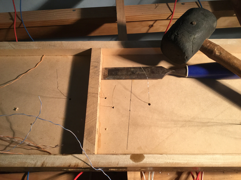
I'm taking advantage of a bit of quiet time to get some railway done. Doesn't feel like I'm cracking on, painfully slow, especially the wiring, but progress IS being made, albeit with three steps forward and one step back.
Cheers
Marty
Posted

Site staff
Fudging Gormo? It's modeller's licenseNice bit of fudging there Marty :thumbs:thumbs:thumbs:thumbs
:cheers Gormo

Nice bit of track work there Marty :thumbs
Ed
Posted
Full Member
Posted
Guest user
Posted
Inactive Member
Ahem…..er…ah….yes….modellers license….yes….that`s quite correct as pointed out by Ed and rightly so……my goodness gracious!!!
My apologies chaps!!!……:oops::oops::oops::oops::oops:
:cheers Gormo
"Anyone who claims to have never made a mistake, never made anything!!"
https://sites.google.com/site/greatchesterfordmodelrailway/home
https://sites.google.com/site/greatchesterfordmodelrailway/home
Posted
Full Member
Might need some help here… at least some confirmation that I'm heading down the right track :cool:
To change the points on the double slip the throw bar moves approximately 1.5mm, The SEEP PM1 point motor's actuator bar moves a maximum of 6mm. To be able to get a good connection between the auxiliary switch contacts on the SEEP the actuator bar needs to move at least 4mm.
Although I'm using a 12mm thick baseboard to allow the SEEP rod between the actuator and points throw bar to "flex" a little on the normal points, thus allowing the auxiliary switch contacts to engage, I'm thinking that the double slip points look a bit fragile and aren't going to stand up for long to a full blooded SEEP 6mm "Wham" when all that is needed is 1.5mm!
So a mechanical linkage has been fettled up by engineers Bodgit & Scarper with an offset pivot point to convert the 6mm SEEP movement to double slip 1.5mm.
Thin 0.5mm brass plate, 6mm wide and 40mm long has been used as the linkage and a Peco point motor extension bar has been epoxied at right angles to the linkage plate. The components are shown in the photo. The expoy is being given 24 hours to cure before assembling the linkage.
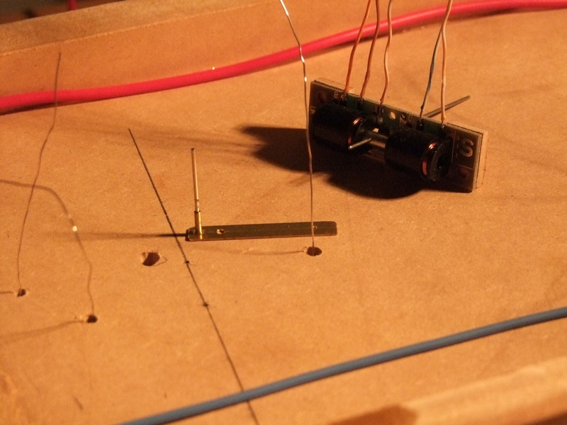
A further photo of the assembled linkage will be forthcoming in due course.
cheers
Marty
Posted
Site staff
Hadn't realised that the movement of the tie bar in N was so small.
Ed
Posted

Full Member
Cheers MIKE
I'm like my avatar - a local ruin!
I'm like my avatar - a local ruin!
Posted
Full Member
Are you having problems with the double slip wiring Mike or just the scissors?
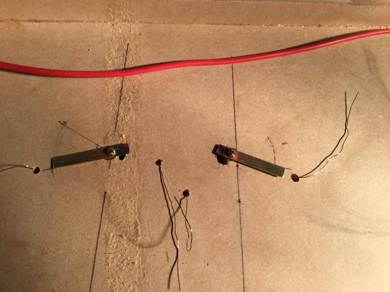
I've just ducked into the layout room to test the linkages Bodgit & Scarper have put together and while "glued" it certainly is, rigid I feel it is not and I'm wondering if they would have been better soldered rather than using epoxy?
Any thoughts?
Cheers
Marty
Posted

Banned
I would go down the solder route. Possibly better in the long run. I once used a pivot to connect two cross-over points together and ran them off one solenoid. It worked a treat, although I used rectangular brass tube with the point motor pins soldered in place through both sides of the brass tube. I can tell you it was still working A1, right upto the point in time of dismantling the layout.
Cheers, Gary.
Posted
Full Member
…and the epoxy didn't work, not rigid enough…
Now to scrape the glue off, clean and then solder the parts and see if that works.
Marty
 Last edit: by Marty
Posted
Inactive Member
Yep ……solder is the way to go.!!
Would it be possible to replace the Seep supplied connection to the tie bar with something more flexible / springy???. …….wire in other words…….maybe 1.0mm or less…..possibly guitar string….I`m not sure of N scale dimensions or requirements. It would give you a bit more tolerance without stressing the parts. The throw could exceed 1.5mm but the flexibility would absorb the excess and act like a spring.
:cheers Gormo
"Anyone who claims to have never made a mistake, never made anything!!"
https://sites.google.com/site/greatchesterfordmodelrailway/home
https://sites.google.com/site/greatchesterfordmodelrailway/home
Posted
Full Member
There is a bit of twist and flex in the 0.5mm plate, but I'll bear a more flexible link wire in mind if things go awry.
Cheers
Marty
Posted
Full Member
GEM 1005 Mercontrol Omega Loop Wire Pack of 6 loops
You can "bend yer own" in piano wire (if you're desperate)
Cheers MIKE
I'm like my avatar - a local ruin!
I'm like my avatar - a local ruin!
Posted
Full Member
At the moment a re-fabrication of the linkages with solder seems to have done the job…
Now to add the motors…
Cheers
Marty
Posted
Full Member
No actually use some cousins of theirs, Bodgem and Fudgit or for rolling stock, including locos, then it's Bashem and Hackitt.
Strange though, they use the same motto, "Nil Fixit Seducem" (which can very loosely be translated as "If ya can't fix it, do the other thing")
Cheers MIKE
I'm like my avatar - a local ruin!
I'm like my avatar - a local ruin!
Posted
Full Member
Marty
Posted

Inactive Member
1 guest and 0 members have just viewed this.