N Gauge - Newcastle Emlyn****
Posted
Legacy Member
:thumbs:thumbs;-):cool:
my webcam link http://86.19.184.67:8080

Posted
Inactive Member
Ken
'It don't mean a thing if it ain't got that Swing'
Posted

Inactive Member
Posted
Full Member
Always try to look on the bright side of life!
Barney
Barney
Posted

Inactive Member
Brilliant photo……you have an artistic eye methinks. Look out Chris Nevard.
You know what Marty???….I have a DVD somewhere created by famous Australian photographer Ken Duncan. He gives advice on how to take good pictures. One thing he mentioned that stuck with me was, you don`t have to spend thousands on good equipment to take great photos, just learn to use what you have.
Well you`ve certainly done that….most impressive. :thumbs:thumbs:thumbs:thumbs
:cheers Gormo
"Anyone who claims to have never made a mistake, never made anything!!"
https://sites.google.com/site/greatchesterfordmodelrailway/home
https://sites.google.com/site/greatchesterfordmodelrailway/home
Posted
Guest user
More like picture of the year !!! Fantastic mate ,so atmospheric just makes you want to walk under that bridge to see what's on the other side
Cheers
Matt
Posted

Inactive Member

Marvellous!
Max
Port Elderley
Port Elderley
Posted

Full Member
:oops::oops::oops::oops: Gentlemen, thank you…. I got lucky… take lots is my motto…. one of 'em might be OK. ;-) Thought it was worth sharing.
For the benefit of those interested in wiring N scale electrofrog points for polarity and other electrical type musings the following is a bit of a "how I'm doing it" with a little test bed being worked on sporadically before tackling the LLandyfriog Junction plank again.
It's not original and I'm in debt to those that have gone before and have shared here and elsewhere.
It is, however, ground breaking stuff for ME and I'm more than happy to have discussion on it.
Those who know how may wish to look at something else for a while.
A while back was a post showing a working sheet of ply designed to assist in cutting rails and soldering wires and for completeness here it is again as a starting point for this post.
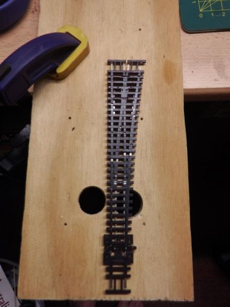
There was some discussion around the method of removing the plastic sleepers from the underside of the rail to facilitate soldering droppers to the stock rails and across to the closure rails. You can see in the above photo that this point has been modified accordingly, staggered in an attempt to preserve the strength of the point, just above the point blade elbows.
Below shows the point with the dropper wires attached. Orange for track positive, Blue for negative common return and green from the relay to switch the frog.
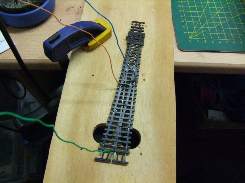
Then, clamp the point to the working ply with the rails to be gapped over the holes. Feed the blade of a piercing saw through the hole and the point next to the rail to be cut. Connect up the saw and cut… carefully. Below the closure rails have been gapped (Red arrows) and the positive track feed (orange arrow) and common return (blue arrow) can just be seen under the point.

More over the weekend all things being equal….
cheers
Marty
Posted
Full Member
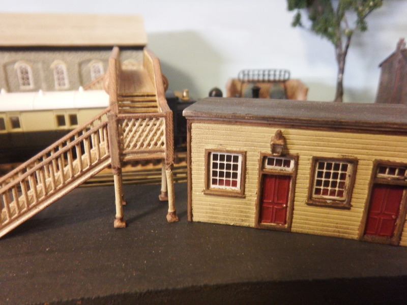
It was the same paint, from the same tube and it is reasonably similar, however, and probably enough to make the difference, the station shelter building was pre-painted in red, where as the bridge was white.
Both had an undercoat of grey primer and then the top coat of beige sprayed on them which was meant to give a consistent base for painting.
The other thing is that the highlights on the bridge were painted with the acrylic a little watered down to help the flow. Maybe that is why it appears lighter.
I'm going to claim a couple of years difference between paintings and a different tin of paint was mixed up for the bridge.
It'll do me.
cheers
Marty
Posted
Inactive Member
I`ll stick around and wait for the next edition.!!!!!
:cheers Gormo
"Anyone who claims to have never made a mistake, never made anything!!"
https://sites.google.com/site/greatchesterfordmodelrailway/home
https://sites.google.com/site/greatchesterfordmodelrailway/home
Posted

Full Member
I had to print it again Marty (particularly as I was late again:oops:)………..absolutely stunning…….probably one of the most charming and natural model railway shots that I have ever seen……..definitely worthy of the full livestock award:G'day All,

Iphone 4 at track level….
More soon…. I hope….
cheers
Marty


:cheers
Posted
Full Member
I wouldnt worry about about the paint shade at all
For your time period GWR light and dark stone were both made from a mixture of Iron Oxide and White Lead………mixed on site to match shades from a colour card……………..I rest my case!:lol:
Regards
Posted

Banned
With the issue of paint, could it be that the station building is a mass of wall, reflecting the colour better, making the colour much more solid. Whereas the lattice bridge has a lot of little panels with a lot of light around each piece making them look a lot lighter ??
I do like your alternative excuse. A mix up of paint tins seems quite plausible. :thumbs
Cheers, Gary.
Posted
Guest user
Toto
Posted

Full Member
but THIS I really like……
So do I
It's shots like that which I come back to for that extra bit of inspiration while I'm dealing with my own little N-gauge project and cursing the tree-stumps I have for fingers!

Posted
Full Member
You guys know how long it's taken to get the layout to a point where a photo like that can be taken.
I'm very pleased with it and have a thought to print it and make it into a "find the scene" game for visitors… just something else to do maybe!
The paint colour has been put to bed thanks to your input. Iron Oxide and white lead matched to colour cards eh? I'll never stress over trying to match GWR light and dark stone again. :lol: The associated surfaces, colours and available light always effects the perceived colour, optical illusion almost and it's a topic worthy of discussion.
Rick, all power to your thumbs mate, I'm watching Boghouses develop and it looks OK to me. Glad you got that 08 sorted out.
cheers
Marty
 Last edit: by Marty
Posted
Full Member
Walking through the steps here will help of course… hopefully :roll: Might help somebody else too. Or get me some help.
Here is a SEEP point motor, (firmly held by Jeeves, my helping hands) wired up for my particular application which is a bit non-standard. Lets see if the following makes sense.
Far left - twisted orange (the colour is a bit washed out) = Solenoid for straight route
Far right - solid orange = Solenoid for divergent route
2nd left - twisted blue = Solenoid motor common return.That much is normal setup for point actuation I believe.
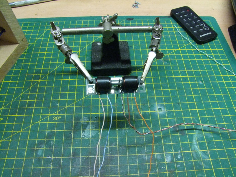
Then the wires for the accessory switching are in between the solid orange and twisted blue.For activating the relay, which is a N/C (normally closed), N/O (normally open) type, all that is needed is voltage from the accessory switch to power the relay magnet which then changes the N/C relay terminal to open and the N/O one to closed.
Changing the N/C to Open breaks whatever circuit it is part of and completes the circuit of the N/O one. Just like a switch.
The relay is in the first state N/C = closed, N/O = open at rest, that is, without power.Apply power and it changes the state.
So…. the twisted brown wire is positive power from the 12vDC bus, the solid brown wire is connected to the relay positive.
With the point set for straight route there is no power applied to the relay (the accessory tab for that routing doesn't have a wire attached to it in this case because it's not needed.)
With the point set for divergent route the throw bar of the point motor completes the accessory switch circuit and power is applied to the relay.
In this case a 4 pole relay. That means 4 things can receive power when the point is changed to divergent route.
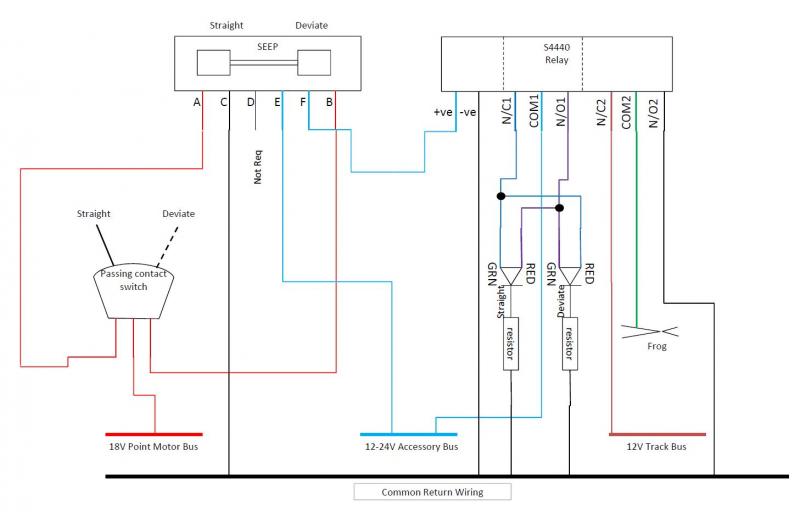
The plan is:
Pole 1) Switching the frog polarity on the point.
Pole 2) Changing control panel LED indicators for point direction Red to Green and vice versa.
Pole 3) Closes a down starter signal lock out circuit to allow the signal to be activated.
Pole 4) Closes an up Home signal lock out circuit to allow the signal to be activated.
The circuit looks mostly like this. The resistor arrangement on the LEDs have been modified and the relay now has 4 poles rather than the 2 shown.
For a beginner who'd never played around with relays before it's a nice challenge and I'm having fun.
More tomorrow maybe…
Posted

Full Member
Mike
Pig Hill Yard - a small Inglenook shunting layout for my boys, in 00.
Pig Hill Yard - a small Inglenook shunting layout for my boys, in 00.
Posted

Full Member
Picture is superb.
Seep wiring looks sound, as for mounting the seeps I use a 3 - 5 mm foam pad as a spacer between the seep and the base board, as I have had issues with them binding when mounted flush. Also Doofer / Chubbs made a simple tool out of a peg with a notch to hold the seep in the central position when fitting, as you say you haven't got a lot of movement .
If you haven't already bought the seeps, r/c servo's are accurate, easy to setup - with the appropriate hardware, and are gentler on the point.
Paul
Posted
Inactive Member
Very quiet, as well.
I originally started looking at them when solenoids started breaking the Code 75 turnouts.
The point rails were breaking off the throw bars.
Max
Port Elderley
Port Elderley
1 guest and 0 members have just viewed this.