Johns 7mm Layout
Posted
Full Member
Cheers Pete.

Posted

Site staff
Paul Bartlett's Photographs | BR Standard Shock vans VSV ZDV ZYW (zenfolio.com)
Paul Bartlett's Photographs | BR (GWR design) shocvan (zenfolio.com)
Facinating.
Ed
Posted

Full Member

John
Posted
Full Member
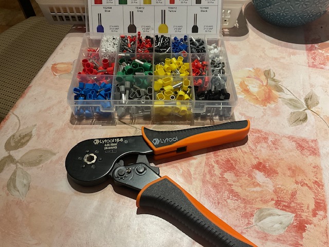
The ferrules go over the stripped wire ends and are crimped:
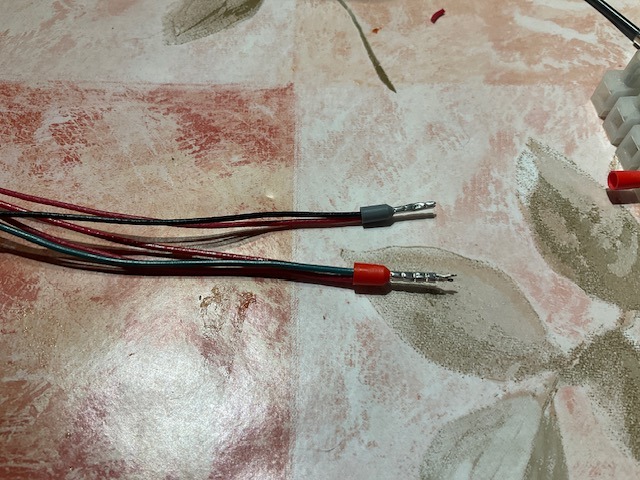
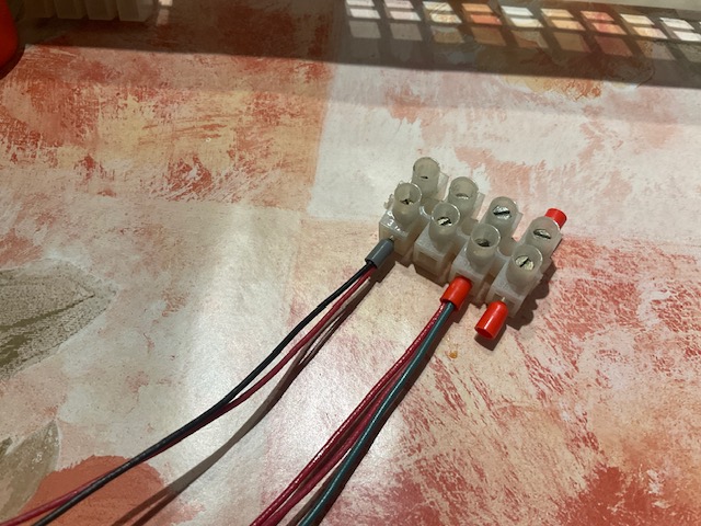
They can then be inserted into the choc blocks with more reliability than previous, or at least that's what I hope:
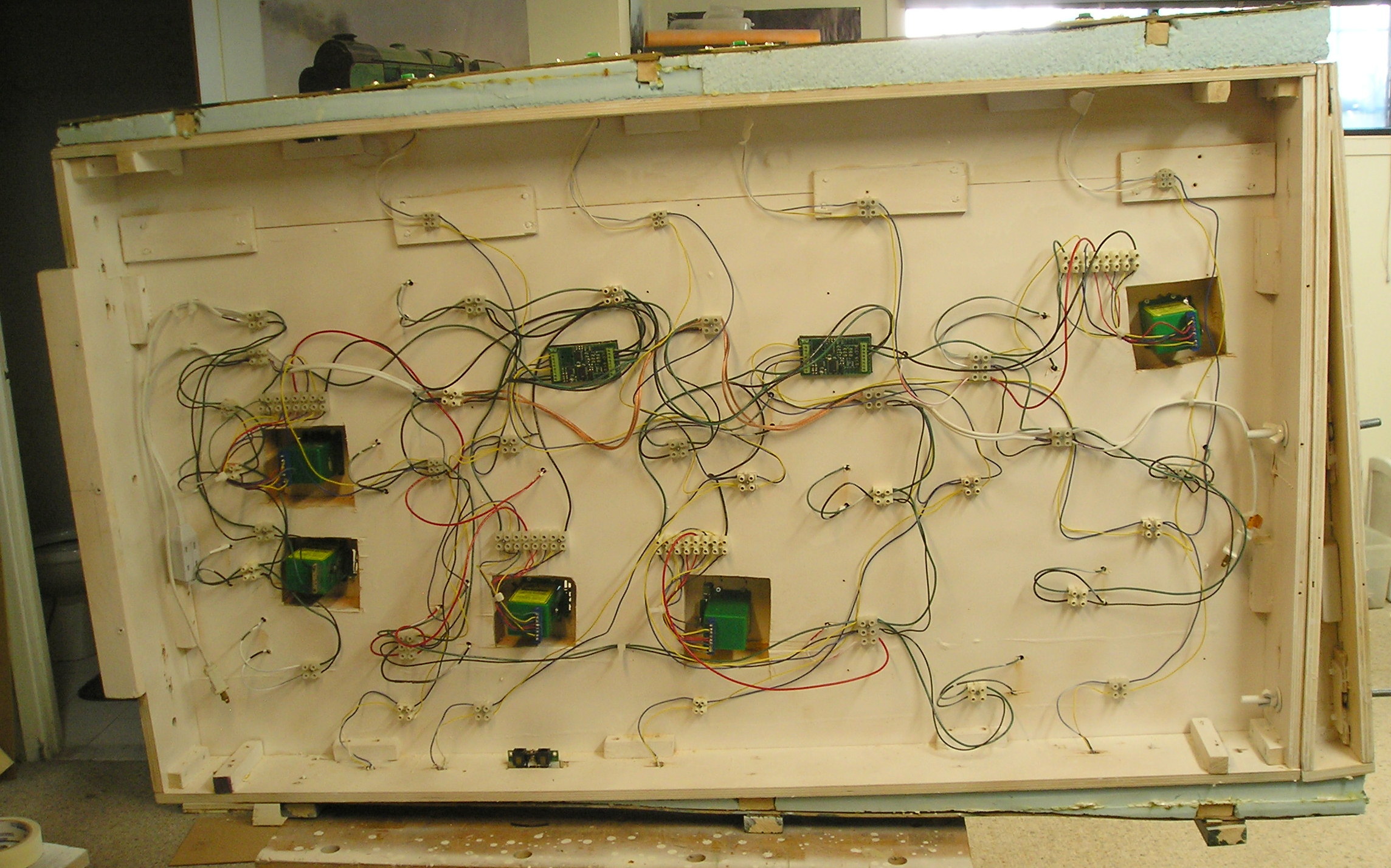
I got through the first board today:
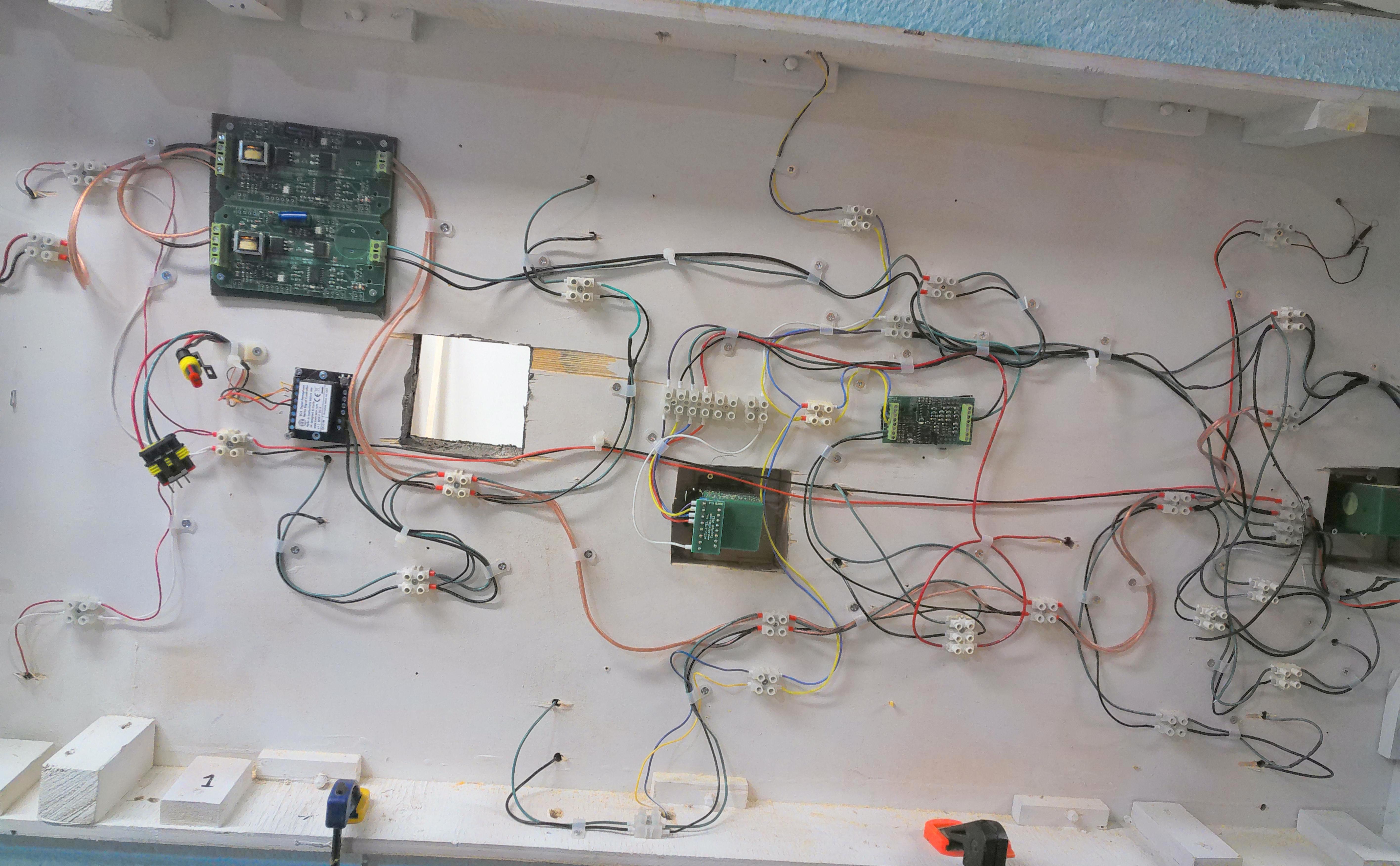
I should stress that the layout is DCC.
I added a new edge connector to the Tortoise motor in the middle. This has screw connections and the edge connector is customized to the Tortoise board. No soldering or packing. This addition makes the Tortoise exactly equivalent to Cobalt.
Just above and to the right is the Wabbit stationary decoder for the Tortoise. I actually have the Wabbit driving three Tortoises, the main one for the turnout that you see and two slave Tortoise motor synchronized to operate catch points.
The boards in the top left corner are short protection. Since I had two in (from probably 20 years ago), I decided to use them. One is for the main power buss, the other powers a buss for the Wabbit decoders.
Under the boards is the stationary decoder for the Peco signal. It is not installed for transport.
At the top and bottom, connected by blue and yellow wires, are momentary push buttons. These are wired to the Wabbit and when pressed once (not continuously) the Wabbit sends 3 secs of 12V DC to the Tortoise.
As I surveyed the wiring, I purged as much of the solid core wire as practicable, replacing it with stranded.
I also went around and used plastic screw clamps to get the wire under control.
I thought it might be useful to provide this info, hope it's not too boring.
Any questions?
John
John
Posted
Full Member
Roger OO DC Steam
Posted
Full Member
Anyway, I have tons of these on the layout and I'm not about to change now. They do work well and the ferrules should make things even better.
The club is using the same things for their big layout.
John
John
Posted
Full Member
Cheers Pete.
Posted
Full Member
John
John
Posted
Full Member
Cheers Pete.
Posted
Site staff
Brossard said
As I surveyed the wiring, I purged as much of the solid core wire as practicable, replacing it with stranded.
From “Post #288,584”, 29th August 2023, 6:53 pm
Just wondering why you've removed the solid core wire John.
Ed
Posted
Full Member
This has become a travelling layout and as such needs to extra reliable.
John
John
Posted
Site staff
Ed
Posted
Full Member
peterm said
You're right, John. I need all the help I can get. The wiring works well, but if I have to trouble shoot, I'm in trouble. I started out determined to make the wiring tidy this time, but the usual thing happened.
From “Post #288,598”, 30th August 2023, 7:35 am
I think it takes perseverance and patience to get the wiring right.
The second board that I started looks awful but I hope to make it a lot better.
Since this was taken even more wiring was added.
Being able to follow the wiring routes will aid troubleshooting. Some labelling as well. I trust you have a wire colour convention.
John
John
Full Member
Yes, I certainly have, it's called anyfing goes. ;)Brossard said
I think it takes perseverance and patience to get the wiring right.peterm said
You're right, John. I need all the help I can get. The wiring works well, but if I have to trouble shoot, I'm in trouble. I started out determined to make the wiring tidy this time, but the usual thing happened.
From “Post #288,598”, 30th August 2023, 7:35 am
The second board that I started looks awful but I hope to make it a lot better.
Since this was taken even more wiring was added.
Being able to follow the wiring routes will aid troubleshooting. Some labelling as well. I trust you have a wire colour convention.
John
From “Post #288,618”, 30th August 2023, 12:49 pm
Cheers Pete.
Posted
Full Member

Even more complicated now than before. I have added lamps since the first picture was taken so that takes a fair bit of wire (red/black).
Next job is to make the interboard connections.
John
John
Posted
Site staff
Ed
Full Member
Wiring a layout is like a "join the dots" puzzle.
John
John
Full Member
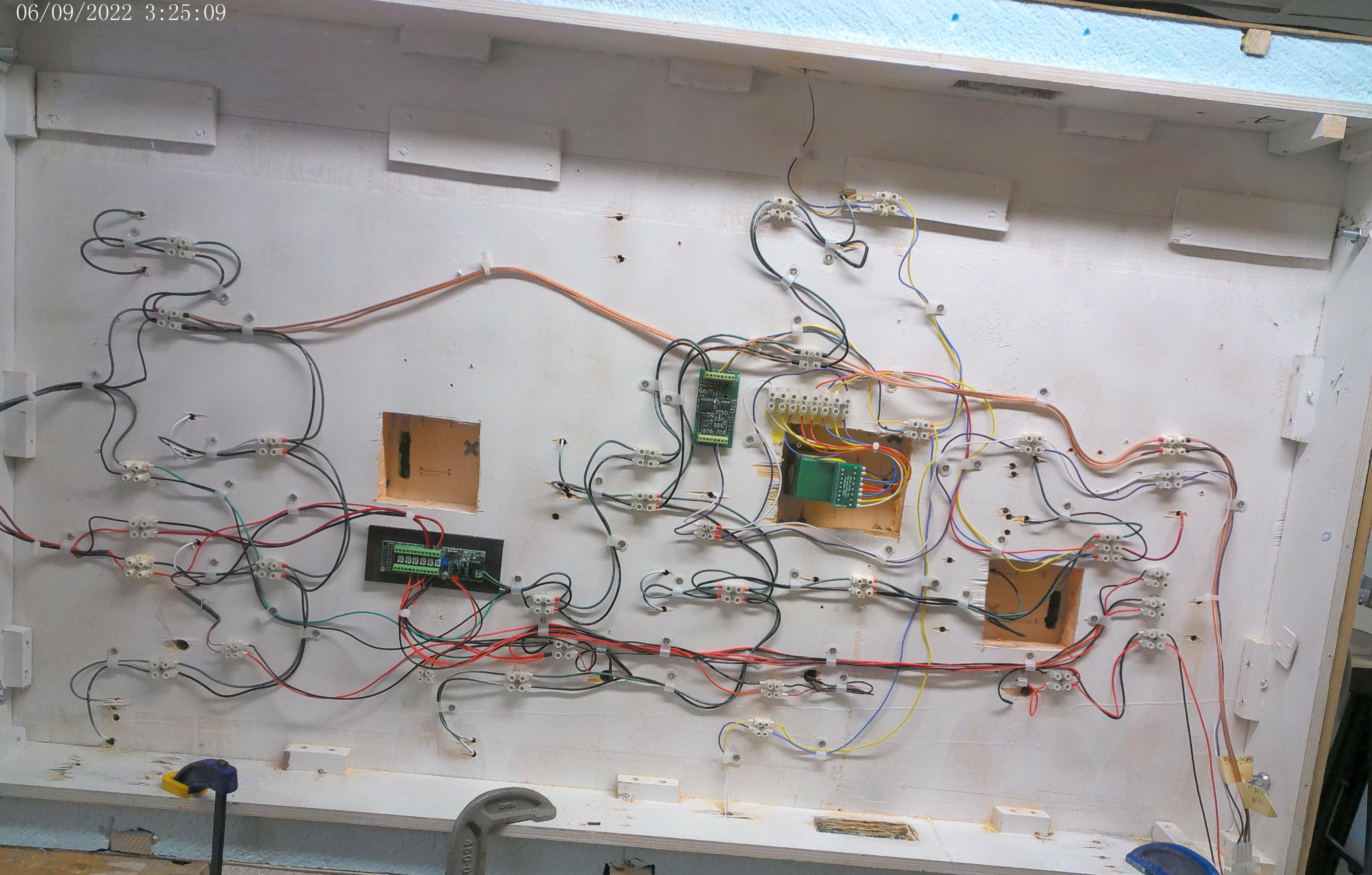
The thing to note here is the power distribution board below the empty square hole (these holes are a legacy of the track changes that have taken place). I'm quite impressed with it. DCC comes in from the right (green/black wires). There's a 3 position switch which permits the output of 12VDC or 3VDC (I forget the other, probably DCC). This board powers the LED lamps rated for 3VDC.
I have actually distributed the power this time, trying to keep the number of lamps connected to a single power output to a reasonable amount, 3 or 4. Therefore there are lots of red/black wires.
Previously I had connected ALL the lamps to a single power output and they were pretty dim. My thought was that there might be too much line resistance. I don't know if this arrangement will be any better, just have to try it.
Still have to connect the interboard connectors on the right. They're done.
John
John
Full Member
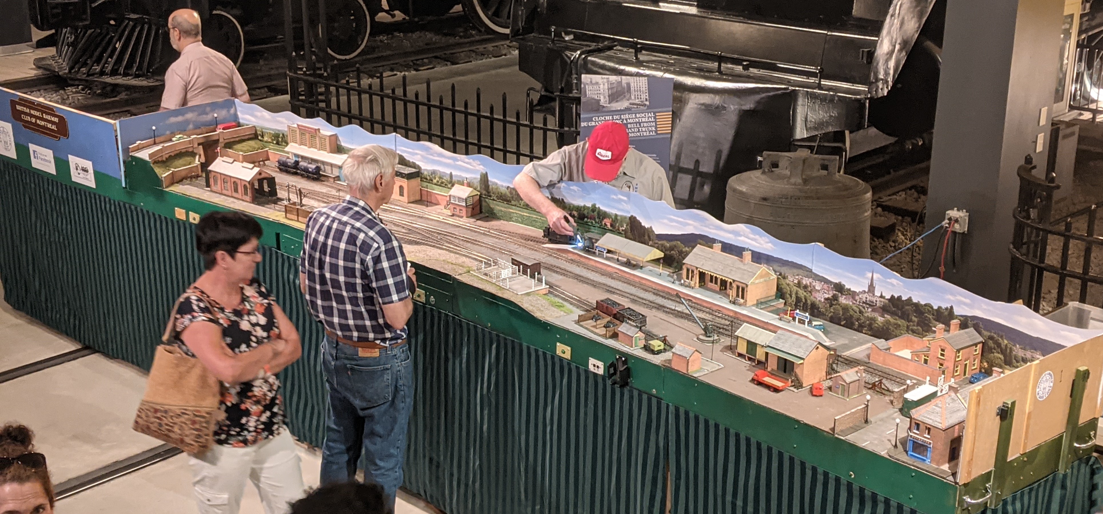
Credit D. Finch
Good overall view of the layout. You can see one of the operators using a torch to do some coupling.
John
John
Posted
Full Member
Cheers Pete.
1 guest and 0 members have just viewed this.