H0 Scale - South Shore Line
Posted

Full Member
EVERYTHING is cheaper than the Volvo version but, if you think you've got Volvo problems, try bringing one to France and asking them to service it !! :shock:Nah … Marty will do it first time.
I once made a dog guard for the back of the estate using the same principle.
Cheaper than the Volvo version.
A brand new Mercedes would be cheaper …………….:twisted:
'Petermac

Posted

Full Member
I had a a pre-MOT check.
They quoted £680+Vat for necessary repairs.
Fortunately there was an MOT Official sitting next to me in the waiting area.
His advice, take it elsewhere.
I did - no repairs necessary.
Posted

Full Member
I have some of the "rock" moulds but haven't tried using the "Hydrocal". I presume it's lighter than normal plaster.
Yes it is much lighter than regular plaster, but still has some weight to it. When I pick up that section of the cliff, I must use two hands now, as it is a bit heavy with only one hand.
In regards to the supporting brackets, take a look at the last photo I posted and compare it to the photos earlier. You will notice that I have reduced the height to only two bars. Most of you won't have the issue I have because your layout is mostly flat, so a two bar support would work fine. On my layout I have sections that (from the underside of the top of the baseboards to the top of the layout) go from 3" to over 12", so I need to be adjustable. That is why the vertical joints are not soldered.
Wayne
Posted
Full Member
I have tied in the tunnel portal and nine inches of tunnel, on the right of the quarry to the quarry itself, so now when I lift up the quarry the portal comes with it. The lift up quarry is now keyed to sit in one spot and cannot move around, so now I can begin working on the edges, to mate them with the surrounding sections.
For those of you who are new to this thread, I am making the layout in sections that can be lifted out for access to wires, connections, track, etc. Each section has to be keyed so it goes back in the exact location each time, and hopefully the "joins" are almost invisible. So far I am happy with the ones that are done.
Merry Christmas Everyone!
Wayne

Posted
Full Member
I do like the idea of these removable sections - a necessity given all your tunnels - but they can be the very devil to disguise after a few "lift-offs".
'Petermac
Posted
Full Member
For instance, by removing the adjacent sections first, I can easily get my finger on the edges to grab it. I am thinking that is the way I will end up with this particular section, but just in case i always put in the molly bolt.
In regards to the lift off joins being hidden, I have a couple of spots where there are three lift offs coming together within an inch of each other. The gaps look fine at this point, but i do not have the grasses and shrubs on them to help out. Hopefully they will be fine when that is done.
This particular lift out is located in the water. :twisted: I have to place them where I believe the balance point is located. I guess I could always put a boat over it!

Wayne
Posted
Full Member
That Wayne, is a brilliant idea. :pathead……………………………………….
This particular lift out is located in the water. :twisted: I have to place them where I believe the balance point is located. I guess I could always put a boat over it!
Wayne
'Petermac
Posted
Full Member
Now this has to dry for a few days before I can move it. Mostly because there is quite a lot of sculptamold and some of it is thin in spots. The thick spots need time to dry out and the thin spots need time to get hard.
Wayne
Posted

Site staff
Ron
NCE DCC ; 00 scale UK outline.
NCE DCC ; 00 scale UK outline.
Posted
Full Member
One thing Wayne is that while you are waiting for that to dry, etc, there is usually plenty more things to do re the layout.
Your absolutely right Sol,however this particular instance my time is being taken up by my grand daughter. She's here right now making Christmas cookies with Grandma.
You would think I could sneak out and work on something, but she is too quick for me. She's 7 years old and I don't have a chance!
Wayne
Posted
Full Member
Posted
Full Member
The rock face, as it goes past the tunnel portal turns and goes parallel with the edge of the layout for almost another four feet. There is a track there also, so that rock face will be very vertical. I have a photo that someone sent me that shows a train running along a ledge barely wide enough for the train. The walls, both above and below the train are vertical. It looks like a mile down to the canyon floor from the train. An awesome photo that has obviously inspired me.
I have heard about the aluminum foil technique, I think on this forum. I can't remember who was doing it, or even if they actually did it, or just talked about it.
At any rate it does sound interesting. I have several rubber moulds from Woodland Scenics that do an excellent job of making rocks. The only problem is after you make several out of the same mould, even after turning them upside down, they become too repetitive.
It is a very simple procedure to make the rocks from the moulds. The only issue is you must shim up the mould to get it to sit level, or you will have a mess on your hands. I would think the aluminum foil would have the same issue.
That said, I just may give the foil a try! If nothing else, everyone here could get a good laugh from it!

Wayne
Posted

Inactive Member
A friend of mine loaned me his set of Woodlands Scenics moulds and I found that by breaking up the larger ones, I was able to make some "New" looking pieces, which can also be turned.At any rate it does sound interesting. I have several rubber moulds from Woodland Scenics that do an excellent job of making rocks. The only problem is after you make several out of the same mould, even after turning them upside down, they become too repetitive.
Max
Port Elderley
Port Elderley
Posted
Full Member
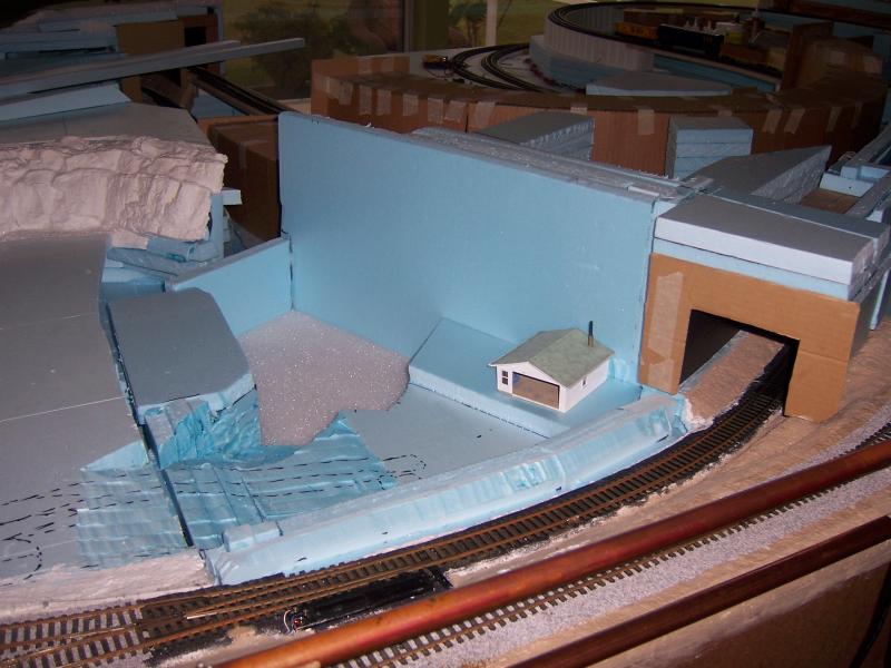
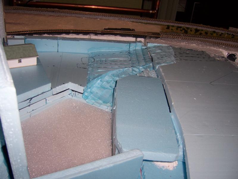
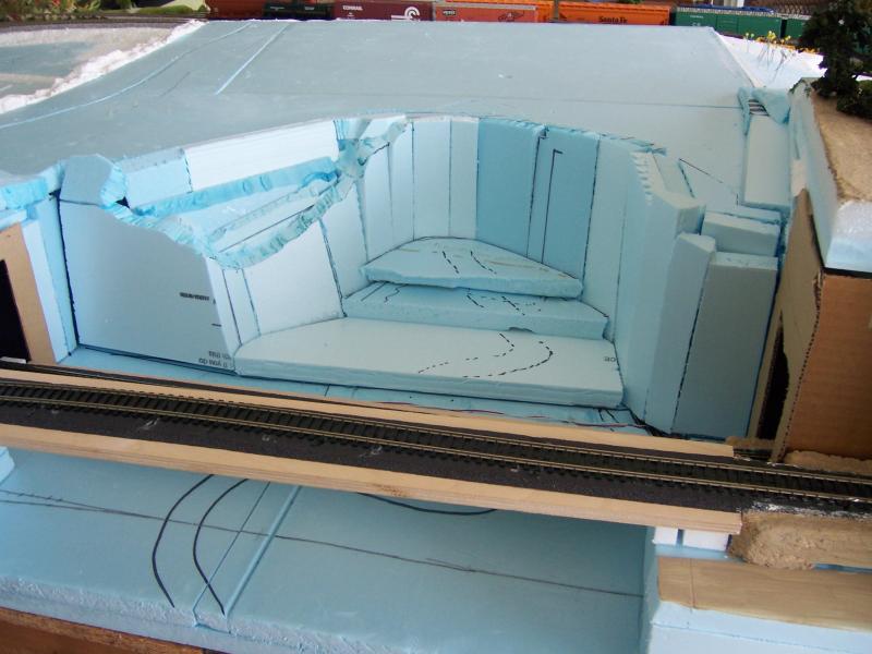
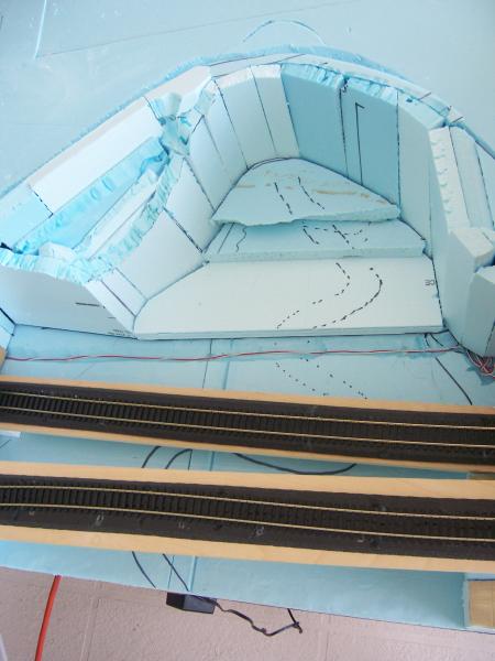
The first photo is a gorge that will be a lot of rock and yet quite a bit of green weeds, trees, even a small creek that winds around aimlessly. I may yet do a little more shaping of the gorge too, maybe a cut in on the right side, like there is on the left side. Haven't decided yet.
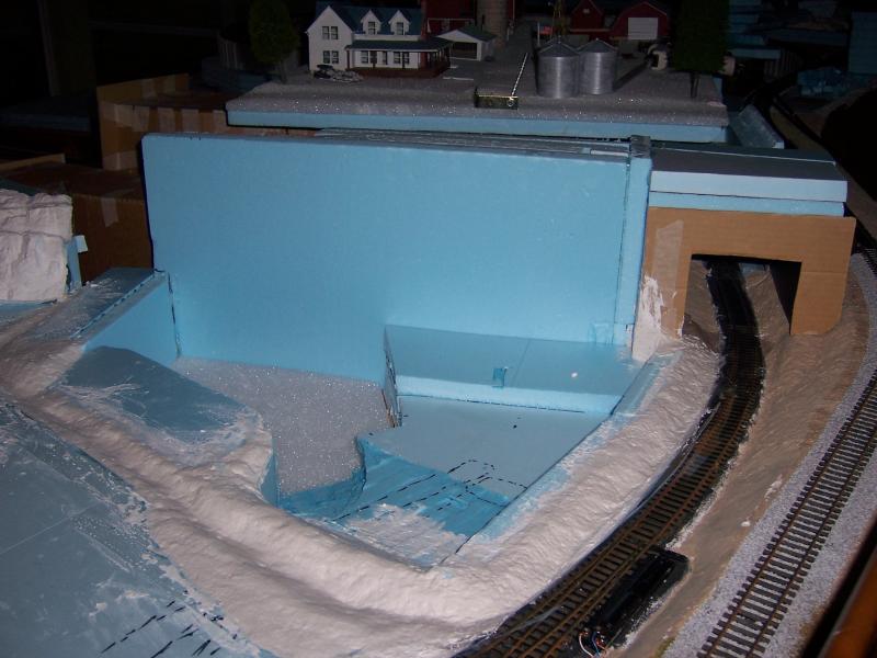
You can see the proposed creek in the second picture. The third picture is just an overview so you can see where everything is located.
Now that the majority of the land contours are in place I will be painting over the blue foam with browns and greens, which should help the eye see the contours better, and hide all that blue color that I am getting tired of looking at!
Wayne

Posted
Site staff
The small problem is that by the time you get to the end, you realize that what you started with is now NBG as your techniques, etc have improved as you progress.
Ron
NCE DCC ; 00 scale UK outline.
NCE DCC ; 00 scale UK outline.
Posted
Full Member
What have you used to stick the foam sheets together - they don't look to be a tight fit so I'm guessing it can't be ordinary glue ? Also, what do you plan for the cascades on the creek ? They'll look absolutey great (maybe a fisherman in there somewhere catching salmon as they leap the falls:roll::roll:).
'Petermac
Posted
Full Member
As for the winding creek, a fisherman or two, plus some kids playing in the creek, maybe some hikers and campers. Lots of things to choose from. I've always liked winding creeks.
Wayne
Posted
Full Member
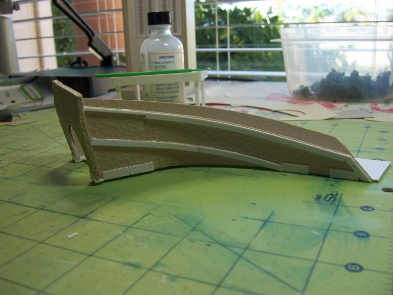
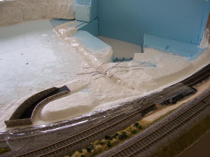
I had to get this done because it must be removable with the section it is located in. You can see the split lines in the first photo running along the track then turning and going up to the top of the photo on the left side, for that removable section. I decided that I will bond the culvert to the removable section, so I had to make it so that it came up vertically off the round culvert tube. It turned out not too bad. There is a small gap on either side below the center line of the culvert tube, but I should be able to place a shrub or something to hide it. Keep in mind it is on the inside of the track and the layout is four foot high, so you would have to stand on your tip toes to even try and take look at those two gaps.
The last photo shows a better view of the culvert in place.
Wayne


Posted
Full Member
I also got out the heavy equipment and shaped the #1 green and tee boxes. The owner of the Birchtree Golf Course puts all his money in the first hole, the largest tee box and green on the entire course! I guess that's to draw you in to play.
I've drawn in some rough line to represent the roads and cart path. Just barely enough room to get them in. I will need to make two bridges to get the traffic over potato creek, which cuts across the golf course.
This all needs to set up good and hard before I try to remove either section. I would think sometime Friday afternoon should do fine.
Wayne
Posted
Inactive Member
I like your scenic methods.
The weather seems to be helping the railway development along..
regards,
Derek.
 Last edit: by shunter1
1 guest and 0 members have just viewed this.