Granby Junction 1948 N. Wales
Posted

Full Member
GWR/LMS OO Gauge DCC RR&Co
Having completed the Reception and coaling roads…..the next stage was to add the second baseboard and infill the service roadsAll the work so far had been on the one board……which is wired up and screwed to the joists…….

In addition to the Entry and Exit Roads the TT has a road for the Sandhouse and six roads for the GWR Shed
On the second board I will add a road for the Wheeldrop and 2 roads for an LMS Shed……which would,I believe, be similar to Birkenhead…….joint site but separate Engine Sheds.
None of this can be done until the second board is in position.

I decided against inspection pits for the shed service roads but I do want one for the Wheeldrop siding…….so this has to be marked up and the aperture cut out off site…………I also need to install the tortoise for the carriage sidings
Geometry is not my strong point …….right angles I can handle but the GWR shed will be pie shaped and although I was pretty careful setting up the service roads I was not comfortable that each angle was identical……..a difference of 1/8" at the TT extrapolates to something significantly greater at the end of the 24" service road.
In short I wasnt absolutely certain where the right hand outer wall of the shed would finish up

 ………………….so instead of laying track I decided to build half the shed so I would have a better visual handle on the space available……….not exactly City and Guilds draughtmanship!

So the first job was to get the foundations for the shed set up…….I had already been playing about with levels and determined that two layers of Matt Board (Mount in the UK?) would keep the level just below the code 83 rail
I had thought of covering the top layer with Scalescene paper like I did for the Warehouse but the concrete is more suitable for street scenes….lots of tyre marks
So I decided to try painting the boards a mucky grey……it took a while to get it adequately covered and despite a lot of effort tended to look flat…….rather like painted matt board
My wife suggested they lacked texture.
So I lightly scored the boards and then with the back of a scalpel made the cut a little more obvious …….creating expansion joints

Then using my wife's pastels I highligted the cuts

Rubbed the black into the cracks and added touches of brown and grey

And here it is in position……..The lighting is different but hopefully you can see the effect

I know I should have inspection pits but doubted my ability to cut out the apertures after the TT was calibrated and in any event the track here is code 83 not the 100 on the pits I saved from Granby II……..similarly I decided against check rails. I spent forever doing them on the warehouse but once it was in position (a) you couldnt see them and (b) the slightest error messed up the operation

Half of the area will be covered by the shed….but all in all I am reasonably happy with the effect
Now that I have a level (?) surface I can start assembling the shed

Posted

Full Member
Regards,
Trevor
Trevor
Posted
Full Member
As you probably gathered I am playing catch up here……I will make another post on the actual building of the shed later then I am only a month or so behind real time.
Posted
Inactive Member
WARNING! Model may not be historically accurate due to implementation of Modeller's Licence
Posted

Site staff
Regards
Alan
Born beside the mighty GWR.
Alan
Born beside the mighty GWR.
Posted

Full Member
The concrete is ingenious and the pitched joints just right. :thumbs
If you take out the "builders clutter" and ignore the desk in the first shot in Post# 801 (wow !!), it could be a real railway. The differing tones of the brickwork in the distance, the huge station canopy and that stunning "refuelling" area in the window are amazing.
'Petermac
Posted
Legacy Member
reg
Posted
Full Member
I found the key with the "expansion" joints was the use of pastels……most remained in the incision and the surplus was randomly rubbed into surface……I painted the cut edges so that were there were real joints they merged with the faux ones….given hindsight I should have been more methodical in placing the joints….but hindsight is a wonderful thing
Peter I still have one module of the station roof to add along with the main station building……but I think that will have to be a fall project
So here is a further catch up post………building the half roundhouse (well its a segment rather than a half)
Its being built using components from the Scalescenes two road north light shed. The outer walls are standard Scalescene………2 x 2mm card core, window apertures cut out….. covered with printed paper….. laminated together……. and then finished with buttresses and plinths.

There are no internal walls in the kit so I modified the external walls by cutting the window spaces to the floor creating passage ways between the units
The kit entrance spans both roads…….this would not work with 6 roads radiating from a TT so I used the gabled entrance from the small engine shed that John introduced last spring

Although I didnt start this project until November last year I had a sort of grand design for some time.
I printed out a load of components for the shed, cut the card to size and took it all away on the boat………amazing how much can be done in a marina or sheltered anchorage
Net result I came home with 7 almost completed walls and 6 entrances……almost because I forgot to print the windows! :oops:
With most of the components all to hand, assembly was surprisingly quick

I started off with the centre road and made sure the entrance was exactly at right angles to the track (and central…..I made a template and for greater certainty tested with real locos)
The first wall was attached exactly bisecting the "Pie slice" between the tracks…..buttresses on both sides provided a solid base for glueing and overcame both visually and practically non 90o joints
Only when completely dry (somewhat late in life I am learning to be patient) did I secure the second wall using the same approach.
Once dry the end piece was cut to size and fitted in place
As I suspected there was a variation in the angle of the roads resulting in the end pieces varying in length…….it wasnt quite as bad as I feared although I was concerned it may haunt me when I fitted the roof
So here are 3 of the six units completed

Rightly or wrongly I decided to only have two of the six ends with windows…….I dont think I am going to detail the interior and the windows are pretty grimy anyway.
The small shed comes with exterior vents so I may make some up and put them on the solid walls

The outer wall is at 90o …….primarily to save space .
And from the front:

The beauty of taking progress photos………. I doubt if I would have been able to correct the alignment of buttress #2…….fortunately the glue hadnt dried when I previewed the shot!
At this stage the roof started to really worry me……the Scalescene kit has north lights made up in modules that are parallell to the entrance and spanning the two side walls…….clearly this would not not work with the shape (whatever it should be called) that I am constructing…………fortunately with a little help(:roll:) I found a solution………….next post
The first job was to secure the second board and lay the balance of the service tracks
With the first 3 units built, it was relatively easy to mark out the exact location of the remaining 3 and then check the clearances and mark out the carriage sidings and final point…………….this will be a very big moment in Granby's history :
The Last Spike coming shortly:lol:
Posted
Full Member
Looking forward to see how you tackle that roof though John. It could be a nightmare.
Have you got a gold spike ready to drive in as the last one ? Check SWMBO's jewellery box for a gold brooch pin maybe. Or would that be living dangerously.

 Last edit: by Chinahand
Regards,
Trevor
Trevor
Posted
Full Member
Have you got a gold spike ready to drive in as the last one ? Check SWMBO's jewellery box for a gold brooch pin maybe. Or would that be living dangerously.
Thanks for the kind words Trevor
:cool wink:cool wink:thumbs
What a brilliant idea…..I wish I had thought of it earlier! Anyway your post prompted me to search thru assorted memorabilla and I came up with this
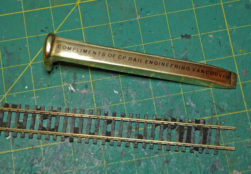
A tad overscale I guess :lol:
:cheers
Posted

Full Member
Really nice work with the turntable and engine sheds.
Cheers
Ted
Ted
Posted

Banned
Cheers, Gary.
Posted
Full Member
This post shows how the roof issue was solved………and it is an excellent illustration of the value of forums like this in creating internet friendships.
I first got to know John Flann, of Little Hintock fame, when he was a member of this forum. He has become a real friend (and neighbour…..he only lives 2000 miles away in Utah :lol:) and a constant source of advice, assistance and encouragement.
After my last post about my roof worries he sent me this:


Pretty impressive and amazingly helpful.

So I discarded my previous fuzzy concepts and attempted to put his idea into practice.
Here are the three sub rooves cut out

I will rig some sort of drain between each roof leading to a grating in the unplanned notch that has appeared between each gable
Coping stones will eventually finish off the tops of the walls and gables
Adapting the North Lights was more than a little tricky
The North Lights for the kit comprise 4 rows each with two lights that completely span the two roads……..our plan is 3 rows each with a single light
These components probably give a better idea of the standard layout

These had to be cut down to a single light for each roof

These shots are of my second batch by which time I had learned the importance of prefolding the cover sheets (at the bottom)!……..they are very finicky and eventually I remembered Doug's (Dooferdog) tip about gently scribing the underside of the foldline
Once the openings are cut out the side pieces are added and the units joined together in a sub assembly

Corner pieces on light card conceal the butt joints
The unfinished strip on the side is where, on the original kit, the sub assembly is glued to the sidewalls
The next shot shows the individual rooves fitted and an aperture cut in the main roof to accommodate the sub assembly

The sub assembly sunk into the roof with flashing added

The roof is clad with Scalescenes Pebbledash which I think suggests the the granite chippings one finds on industrial flat rooves
Now actually installed……the paper is wrapped around in true Scalescene fashion and as the original card was cut to size creates a nice snug fit.

There is a little touching up still to do and eventually some weathering.
The kit comes with some rather flimsy cut out ventilators…..I need to do a bit more work on them to make them more robust.

Overall the effect is exactly what I had in mind so I am pretty happy and more than a little relieved
 .
.
One down………. Five to go
Although first I have to build 3 more sheds……..and we need the last spike! :thumbs
Posted
Full Member
Regards,
Trevor
Trevor
Posted
Banned
Cheers, Gary.
Posted

Full Member
(Excellent result by the way).
I expect you've fixed the pastel with an appropriate spray?
Over the years the pastel will tend to migrate if not.
Great sheds, too!
Posted
Full Member
DD…….. you pose a very pertinent question……and I cannot tell a lie………..I am afraid I forgot to spray the concrete:oops::oops::oops::oops: and its too late now because everything is glued down. I am punctilious about spraying all my Scalescene papers the moment they come from the printer so I have no excuse…………fortunately I brushed and rubbed the pastel well in……but it should have been sprayed and I should have pointed this out in my post so others are not lead astray…….thank you for asking the questionand reminding me :thumbs
Some quick shots to show the uncompleted shed in context with its surroundings…..service roads, Turn Table and Support Buildings

The final baseboard is now in and secured. All the remaining tracks radiating from the TT are in place, wired up and indexed.
The roof has been finished on the partially completed GWR shed covering tracks 4, 5 and 6


The drains between the roof segments are Woodlands scenic I profile painted mucky brown…….I am still fiddling with both the quantity and the best way of fabricating the ventilators

Next to the shed are track#s 3, 2 and 1…………..these will eventually be covered by a continuation of the GWR roundhouse shed
The road with the tracksetta and pit is for the wheeldrop and a small workshop (actually the Scalescene single road shed from which I got the main shed entrances)
Next to that are the two LMS roads……I am a little undecided about the curve…..it was a saw off between having a decent straight run off from the TT and getting the tracks parallel for the 2 road shed…….its somewhat sharper than I would have wished…… its not a huge issue operationally because that road will be used by smaller locos
Finally the big operational plus that will result from this project…..between the shed roads and the existing mainline I have managed to squeeze in 3 carriage sidings……more of this in the next post
Here is a close up of the Ratio wheel drop ex Granby II with inspection pit

I will set dummy track for the Wheeldrop between the hardstanding
I plonked a couple of buildings on just to see how it would look….imagining the GWR shed is extended by 3 more units

The Scalescene Workshop needs some detailing….Chimney/Doors etc but otherwise looks the part. I am less certain about the Metcalfe unit

Its another survivor from Granby II (but only just!) It will need a lot of TLC but even then I am not sure how it will stand up against the Scalescene finish…….perhaps a temporary stop gap until I run out of things to do!

I am not going to be able to place all the buildings that I think would be associated with this size of shed but I will try and scratchbuild some small structures at the back to suggest a booking in office and maybe a mess room. The aim is create a sense that the complex has developed, over a number of years, in a rather haphazard fashion in response to everchanging techniques and demands……..which is what I imagine happened on the prototype
My apologies for a somewhat dry and dusty post……I am trying to complete this update and get back to real time before I gbreak off for the Summer!

Posted
Full Member
I told you to use fixative on that pastel!
Seriously, a grand job and I'm sure all will be well.
I hope my comments on the pastel haven't given you something that will be bugging you on the boat!
Look forward to seeing more.
Posted
Full Member

Regards,
Trevor
Trevor
Posted
Full Member
Simple but so effective.I'm going to have a go at that myself.
Can't say anything about the layout that hasn't already been said…..It's just awesome..:thumbs
Just be yourself…….
Cos those who matter don't mind,
And those who mind don't matter.
Ste
Cos those who matter don't mind,
And those who mind don't matter.
Ste
1 guest and 0 members have just viewed this.