Granby Junction 1948 N. Wales
Posted

Full Member
GWR/LMS OO Gauge DCC RR&Co
I put an electrofrog point in because the "normal" route will be frequently used…….its switched with a peco surface point motor……..and I didnt give enough thought to the wiring…….so the frog polarity is permanently wired to the normal route.There are a couple of workarounds…..I can retrowire the frog (even though it is ballasted now) and change the motor to a regular peco surface mounted with a switch on top………….in the event I took an executive decision to defer a coal schedule:oops::oops:………hence my question about Mangarth………I realised I had masses of sidings all round the layout many of which were currently never visited by a scheduled train……….so for now that little bit will be more of a diorama

Posted
Full Member
Posted
Full Member
Posted
Full Member
Posted
Full Member
I have not removed the links nor have I hooked up the frog wire (I think)…….basically the bottom rail is common and everything else is positive :oops::oops::oops::oops:……….I think the point has a single positive and common feed
I have a vague memory of thinking I could rely on the switch rail to sort things out and then when I hooked up I had a short situation:roll::roll: which I resolved decisively by cutting a common feed………which worked……after a fashion ……..until I tested the ramp
Posted
Full Member
Posted
Full Member
I cut the frog connections and the power now switches…….after a fashion………………….the normal route is fine…… over the frog 16.1v but when I throw the point to the ramp (which is tricky because I was careless with the ballasting) I only get between 5 and 6 v………..I dont think the blade is making great contact but I dont think that is the issue………….never experienced this before……I am sure it is something blindingly obvious:lol:
Posted

Site staff
Ron
NCE DCC ; 00 scale UK outline.
NCE DCC ; 00 scale UK outline.
Posted
Full Member
Phil
Posted
Full Member
Just to be sure - when set to the normal route, you are measuring the voltage between the "common" and the frog and you see your DCC bus level of 16.1v; but when set to the ramp, you are measuring the voltage between the frog and the other DCC bus wire (i.e. not the "common") and you see 5 or 6v - YES?All the point connections are insulated. The frog isnt wired up
I cut the frog connections and the power now switches…….after a fashion………………….the normal route is fine…… over the frog 16.1v but when I throw the point to the ramp (which is tricky because I was careless with the ballasting) I only get between 5 and 6 v………..I dont think the blade is making great contact but I dont think that is the issue………….never experienced this before……I am sure it is something blindingly obvious:lol:
I wonder if you have managed to provide a resistive path from the frog or either of the moving blades, to the stock rail the blades are in contact with on the normal route?
This would have no affect when set in the normal route, but would cause a current to flow when set in the ramp position and if the contact of the blade on the common stock rail is poor, you would see a drop in voltage on the frog.
I have read of this happening with some types of ballast mixed with PVA if it gets in contact with the rails. Others may have experienced it themselves. I don't use PVA on my track, so I am afraid I don't have first hand experience.
If this is what has happened, then DO NOT connect the frog to a switch as you may replicate a similar situation to that experienced by "Novice" in his recent thread!!!
Posted

Full Member
'Petermac
Posted
Full Member
Firstly I use a "sticky" underlay, and then reinforce when everything is in place with acrylic floorpolish. I think there used to be a product called Kleer, but I have one called LTP. Works great and without the movement you sometimes get when applying PVA. Also does not need a wetting agent like washing up liquid as it is already formulated that way.All very interesting stuff (and, to me a little daunting :oops: ). Without wishing to hijack John's thread, what do you use to glue your ballast Geoff ?
Posted
Full Member
Geoff I am afraid you are going to be annoyed with me or at the very least irritated after all the trouble you have taken'Just to be sure - when set to the normal route, you are measuring the voltage between the "common" and the frog and you see your DCC bus level of 16.1v; but when set to the ramp, you are measuring the voltage between the frog and the other DCC bus wire (i.e. not the "common") and you see 5 or 6v - YES?
I wonder if you have managed to provide a resistive path from the frog or either of the moving blades, to the stock rail the blades are in contact with on the normal route?
This would have no affect when set in the normal route, but would cause a current to flow when set in the ramp position and if the contact of the blade on the common stock rail is poor, you would see a drop in voltage on the frog.
I have read of this happening with some types of ballast mixed with PVA if it gets in contact with the rails. Others may have experienced it themselves. I don't use PVA on my track, so I am afraid I don't have first hand experience.
If this is what has happened, then DO NOT connect the frog to a switch as you may replicate a similar situation to that experienced by "Novice" in his recent thread!!!
I am afraid I have screwed up comprehensively. I know this is a warts and all thread but this is going too far.
I really didnt think the wiring thru and this was one of the unlisted dramas in my tale of woe a few posts back…….so I suspect I cut a feed incorrectly………then when I realised my mistake I decided it would take too long to sort out and decided to go the diorama route…….hence my question to you
Because of this executive decision I was less diligent with the ballasting than usual…….normally I ballast one point at a time and throw it at 10 minute intervals to prevent it sticking (please dont ask why I do this)
So this point has adhered to the normal (fortunately) position and now has to be manualy put into position on the other throw…….not the first time this has happened and usually correctable……..but this point is right by the window ledge behind the Overall roof…….. at just about my maximum reach standing on a stool ad leaning on the said overall roof……these scalescene structures are quite solid!!
Sadly yesterday…..acting first and thinking afterwards…….I cut the connections to the frog……not recommended if you are relying on switch blade contact…………….I think the reduced voltage was a result of not doing the job properly……well the this morning I did it properly……..result no power to the frog at all……..the Engine Shed is completely cut off from the world…..so I spent a happy two hours on the stool leaning on the roof trying to solder a bridge for the normal route using Doreens make up mirror so at least I could put the iron roughly in the right place. Finally completed…..the draw bridge is down….the Shed is open for business…….but for the time being the ramp will remain a diorama.
Spent the afternoon working out how to reply to you putting a positive spin on everything………..in the end decided……I cannot tell a lie…………………hopefully this will not put you off advising me on any future problems!
Kind Regards
I couldnt mount a tortoise (I dont normally do blade contact Phil….I agree with you) so I decided
Posted
Full Member
Would you mind telling us which LTP product you use as a replacement for Kleer as I see they do various products.
Appologies John for barging into your thread but it could be helpful to all of us finding a Kleer replacement.
regards
Ron
Posted
Full Member
……………Finally completed…..the draw bridge is down….the Shed is open for business…….but for the time being the ramp will remain a diorama.
…………………hopefully this will not put you off advising me on any future problems!
Sorry to see that you have had so much of a problem with that point - doesn't it always happen at places that are difficult to access.
Glad that you now have the shed area working again.
I find it very encouraging the way we are able to share the ups and downs of our modelling within this forum despite being at opposite sides of the planet, and am far from being put off from sharing experience and ideas.
As I cursed to myself yesterday when I found out that I had assembled and glued together the components of my junction road bridge with the road upside down so that the angled cut at one end did not match the piece it connected to, I reflected that I seem to spend at least as much time correcting for mistakes as I spend getting something right first time!
Posted
Full Member
Hi Geoff
Would you mind telling us which LTP product you use as a replacement for Kleer as I see they do various products.
Appologies John for barging into your thread but it could be helpful to all of us finding a Kleer replacement.
regards
Ron
It is called FLOORSHINE as shown here:- http://www.tilefixdirect.com/product/LTP-6-1
I bought it a couple of years ago from a local tile centre. It was quite expensive, but I have a litre which goes a long way. I dilute it roughly 3 to 1 with water. It sets remarkably solidly, yet is easily dissolved with a little warm water.
Posted
Full Member
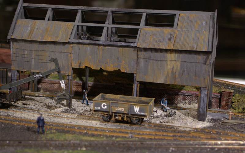
The last post covered the ramp to the coaling station. Next step on the reception road was an office for the yard booking in clerk. This is a modified weigh bridge hut.
To the right are the hand levers for the three way point accessing the Turn Table
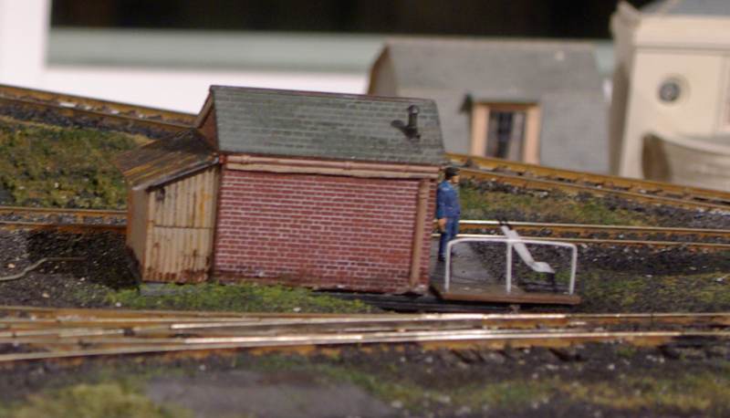
I have already covered the Ash Pit itself but I discovered that during WW II sheds were constructed over the pits to prevent the glow being used as markers by the Luftwaffe. Once the war was over most were quickly taken down……although the one at Didcot remained in place until the 70s……in fact at one stage it was used for carriage storage
I am always on the look out for "time stamps" to better establish Granby's 1947-8 period.l
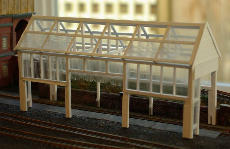
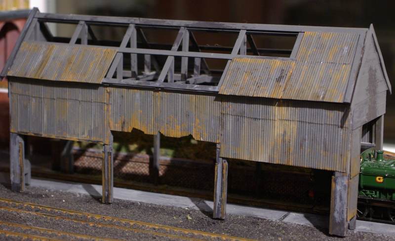
I wanted it to look partially dismantled so Wills sheeets wouldnt work……it had to be a proper structure with plastic strip.
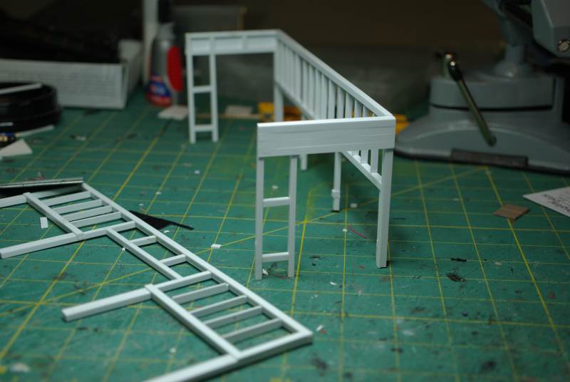
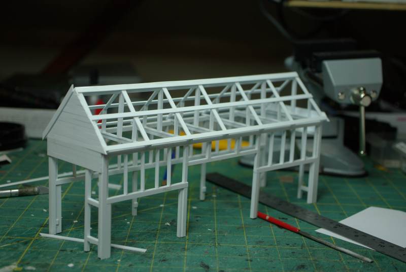
Added some Wills clear corrugate (super useful product)
Sprayed with a sort of metallic grey paint and then lots of rusty weathering washes
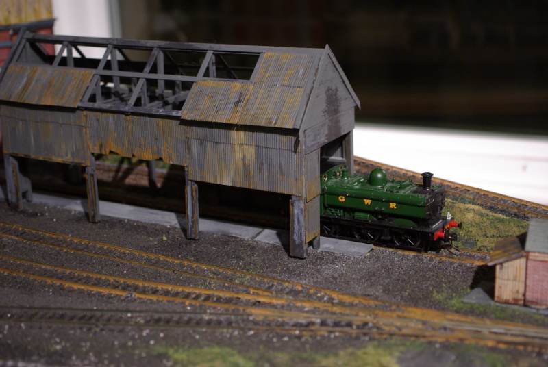
Added the trademark Pannier
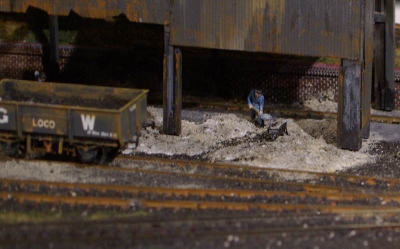
Genuine ash!

I need to take the photoshop seminar then I could get rid of the window!
Dai Morgan hard at work…….he may well be on piece work
Unlike the other Big Four companies the GWR didnt invest very much in mechanical handling equipments, preferring to rely on manual labour………….but some of the larger sheds had rail mounted mechanical shovels
To finish with………….. a couple of black and white shots.
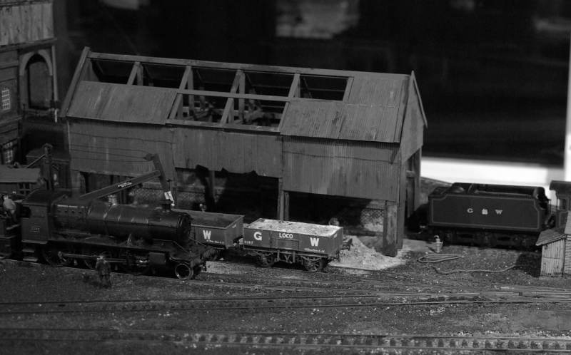

Hopefully they convey, to some extent, the muck and grime that was an inherent part of every steam age shed.
Posted

Posted

Full Member
The aging and weathering are superb:doublethumb
 Last edit: by Chinahand
Regards,
Trevor
Trevor
Posted
Full Member
Barney
Always try to look on the bright side of life!
Barney
Barney
1 guest and 0 members have just viewed this.