Granby Junction 1948 N. Wales
Posted

Full Member
GWR/LMS OO Gauge DCC RR&Co
The map almost encompasses my area, John.I'll look forward to some unexpected excursions West of the Mold Terminus.

Posted

Full Member
Posted
Full Member
Somewhere West your lines will have joined up with the Land Cruise route.
Posted
Full Member

This is the last major build on Granby……there will still be a number of other significant projects….Cynwyd Dairy, Granby Station itself and the adjoining Parcel depot…….but these are all what we call infills in Vancouver. Once the shed is finished I wont be laying any more track
Because it is the end in every sense……the baseboard just clears the door to the garden…….there is absolutely no more space………all those inches I so glibly "borrowed" months ago to ease the station approach or provide a longer headshunt in the goods yard are all coming home to roost
I had originally intended to have a separate entrance and exit to the shed but that had to be sacrificed in order to include a couple of carriage sidings which, having operated the layout for a while,I now know to be essential
I had hoped to leave uncovered the 2 road coal line that links the upper and lower levels (the two lines on the left in the shot above)……..but again this was not possible so, in consequence, there were a whole series of additional design problems to ensure adequate clearance

I use 3/4" ply as baseboard…. and cut up the last bit of the last sheet bought 5 years ago………to create the clearance I bonded 1/4" ply on top so that I could lay some track over the coal line
This shows the baseboard in position with the reception roads roughly in position and the template for the Heljan TT
You can see the entry (and exit) point just to the left of the station roof.
Its not very prototypical in that locos will enter the reception road for coaling etc and then have to reverse twice to enter the shed via the TT!
I have found examples of these three oddities……but never on the same site!
Once I had carefully marked the transistions to the main baseboards it was removed to facilitate track laying, wiring and ballasting
So here is the aperture for the TT cutout and the reception road laid .
 …
…On entering the shed area a loco checks in…..moves over the ash pit (772) then on to the coaling area (773) clears the xover point into the first head shunt and then on to the loop (where there will be a water crane) and over the 3 way point where it can either go back to work or,more likely go on shed via the upper arm of the 3 way and the TT
The centre arm of the 3 way is a siding for the ash wagons

The ash pit was cut out for 3 peco inspection pits

The concrete surround is just card.. scored and painted………….this will be viewed from a fair distance but I think I will also use it for the shed area
Immediately after the ash pit is the coaling area and the plan is to use one of the few relics of Granby II ……loosely based on photos I took at Didcot

This demonstrates rather too well my "Dont bother with the non viewing side" approach………its also very battered……but I have kept all the bits and pieces so I think it may scrub up ok

The head shunt and xover point is just on 1/4" ply and there is zero clearance below so the tortoise had to be surface mounted

I know Max does this all the time and has a better system but this actually works for me. Its an adaptation/modification of the Tortoise remote control combined with a peco surface mount lever

I know the + and - look a bit juvenile but bitter experience has taught me to spend a ton of time working out the desired polarity while you are sitting down with a glass of wine rather than crouched under the baseboard with wire cutters and a soldering iron

Hopefully I am going to have a number of locos all moving at the same time using RR&Co………so the there are 8 detected sections in the reception area……..thats the set up to the left of the Heljan control panel. The detectors to the right are for the shed itself where there will be 8 roads in total……….I am still a couple short so I have a bit of fiddling to do in other areas
Having seen Trevor's wiring I swore that I would never show mine again……but this is tidier than most of mine and does show the underside of TT
in position

It also show the extent of 1/4" ply overhang required to clear the coal line………………more on this in my next post!
Posted
Full Member
Do you have plans for all that wasted space on the ceiling?
Posted

Full Member
Unfortunately, my offerings seldom get beyond the "good grief" stage ………….:oops:
A few "silly" questions.
Whilst I'd guess the numbers on the points identify the points, what do the numbers on the tracks signify ? Is it sections ?
How long are your arms ? It looks like quite a reach from the board edge to those coal lines.
How did you set about cutting the sleepers out for the ash pits ? Whenever I've tried it, I either end up with internal sleeper ends that look like a worn-out saw blade or rails whose gauge fluctuates from broad to narrow and all points in between …..

I'd guess the TT baseboard is quite heavy. Will this remain removeable for servicing etc and if so, how will you lift it out or is it fixed in place once the "modular" build has been completed ?
I wouldn't worry too much about non-prototypical operatins in the shed area. As you say, you've found prototypes for all the "unusual" moves, albeit not at the same location. All you've done is compress them a little. Isn't that what we always have to do in railway modelling ?
I'll watch this development with great interest. :cheers
'Petermac
Posted

Full Member
Regards
Pete.
ECOS2 with RR&Co Traincontroller and a load of other electronics so i can sit back and watch the trains go by.
Pete.
ECOS2 with RR&Co Traincontroller and a load of other electronics so i can sit back and watch the trains go by.
Posted

Full Member
Talking of the coaling stage, is it a 'Mill Lane Sidings' kit John ? The reason I ask is that Santa brought me the N Scale kit and, notwithstanding the 17 A4 pages of very comprehensive instructions, all I've done with it so far is look at the multitude of different parts, some of which are absolutely tiny, with growing trepidation. I think it will warrant a chapter of its own in my Market Havering thread.
Regards,
Trevor
Trevor
Posted

Full Member
[user=6]Petermac[/user] wrote:
May I offer this tip? A block of wood with two rail grooves, guide lines for verticality and a chisel ended Exacto type knife….How did you set about cutting the sleepers out for the ash pits ? Whenever I've tried it, I either end up with internal sleeper ends that look like a worn-out saw blade or rails whose gauge fluctuates from broad to narrow and all points in between …..
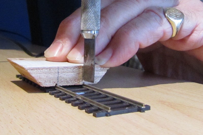
I leave one or two intact to keep the gauge until the length is glued in place then Dremel disc them off.
Pardon hi-jack, John, tell us how you do it so well?
Doug
'You may share the labours of the great, but you will not share the spoil…' Aesop's Fables
"Beer is proof that God loves us and wants us to be happy" - Benjamin Franklin
In the land of the slap-dash and implausible, mediocrity is king
"Beer is proof that God loves us and wants us to be happy" - Benjamin Franklin
In the land of the slap-dash and implausible, mediocrity is king
Posted
Full Member
I had thought of rough-cutting the middle of the sleepers (with the Dremel disc) then tidying up with a chisel point scalpel blade (I've used a No 10 or 11 blade hitherto) to "relieve" the pressure of the cut but it seems I don't need to. :roll:
'Petermac
Posted
Full Member
More splendid stuff, John.
Do you have plans for all that wasted space on the ceiling?
 Working on it DD!
Petermac wrote:
Correct. I use Lenz occupancy detectors that feed back to Lenz decoders. Each decoder handles 8 sections. So 781 means the first section of decoder #78Whilst I'd guess the numbers on the points identify the points, what do the numbers on the tracks signify ? Is it sections ?
Its a first class system…..virtually trouble free…..and essential for computor control . The masking tape numbers all over the place are equally essential for my ageing brain
Very……Orang Outangs have been known to glance at me with envy ( I assume they were looking at my arms. But you do raise a valid point……I use a set of steps to reach over but scenic stuff in the foreground is subject to unplanned modification!How long are your arms ? It looks like quite a reach from the board edge to those coal lines.
The entire shed area is a right angle triangle 5' at the base 6' by the coal line and 7' on the hypoteneuse. There are actually two baseboards but I guess the photos dont show it very well……once the TT board with the majority of the wiring is done and tested it will be fixed and I will start wiring the second.I'd guess the TT baseboard is quite heavy. Will this remain removeable for servicing etc and if so, how will you lift it out or is it fixed in place once the "modular" build has been completed ?
There is space for maintenance under the boards but here any resemblance to an Orang Outang becomes a distinct disadvantage
I have answered the inspection pit query below
Thanks for the good wishes….as always much appreciated
wogga wrote:
Spot on Pete……only the ceiling leftThat's a mammoth task you have embarked on John, but that is the last corner isn't it?
Chinahand wrote:
Another brilliant episode in the development of Granby III John. That's a pretty unique track configuration and it will certainly add some complexity to the operations in that area. The wiring looks suitably complicated but you've managed to keep it very neat and tidy.
Thanks Trevor……..you and Pete are confusing me……:lol::lol::lol:
Not half as much as the guys working there! The space is needed for the coal trains but there will be some crude but cunning bit of cantilevering for additional supportI'm a little perturbed by the positioning of the coaling stage though. Is there another strip of baseboard to go underneath where it overhangs into space at the moment ?
No its scratch built from a couple of Wills water tank sets and brick sheets. I think it would be great if you ran a thread…..I think I have seen a few photos elsewhere of a completed kit and they seemed to have some interesting detailTalking of the coaling stage, is it a 'Mill Lane Sidings' kit John ? The reason I ask is that Santa brought me the N Scale kit and, notwithstanding the 17 A4 pages of very comprehensive instructions, all I've done with it so far is look at the multitude of different parts, some of which are absolutely tiny, with growing trepidation. I think it will warrant a chapter of its own in my Market Havering thread.
Posted
Full Member
Thats a really neat tip Doug…….I am wrestling with the issue of inspection pits for the shed service roads……I was wondering if I could avoid cutting all the apertures out and create a sort of faux pit…….but this would involve cutting out the sleepers
[user=6]Petermac[/user] wrote:May I offer this tip? A block of wood with two rail grooves, guide lines for verticality and a chisel ended Exacto type knife….How did you set about cutting the sleepers out for the ash pits ? Whenever I've tried it, I either end up with internal sleeper ends that look like a worn-out saw blade or rails whose gauge fluctuates from broad to narrow and all points in between …..
I leave one or two intact to keep the gauge until the length is glued in place then Dremel disc them off.
Hmm I fear, however inadvertently, that I have mislead you………..I did mention in the text that I used Peco Inspection Pits I must confess that they were bought :oops::oops::oops::oops:Pardon hi-jack, John, tell us how you do it so well? Doug
They are 4" plastic mouldings supplied with drain holes, covers, steps and chairs……..my contribuition was confined to painting,weathering and sliding rails into the chairs ……………..I feel rather like a magician who has just explained how the lady was sawn in half.
Posted
Full Member
Posted
Full Member
John wrote
Aaagh! The 'B' word, albeit v.small and grey…tee-hee!Hmm I fear, however inadvertently, that I have mislead you………..I did mention in the text that I used Peco Inspection Pits I must confess that they were bought
ddolfelin wrote:
I merely slide the blade right up to the edge of the tiny raised area of the moulded chairs. It's not wholly prototypical, butit'lldo!I was going to ask if the cutting of sleepers included the chairs.
Doug
'You may share the labours of the great, but you will not share the spoil…' Aesop's Fables
"Beer is proof that God loves us and wants us to be happy" - Benjamin Franklin
In the land of the slap-dash and implausible, mediocrity is king
"Beer is proof that God loves us and wants us to be happy" - Benjamin Franklin
In the land of the slap-dash and implausible, mediocrity is king
Posted
Full Member
I remember now that Geoff R did some excellent sleeper cutting for the "pit" on his tube module (I should have realised because that very module is up in my attic as I type this :oops::oops::oops:). I wonder how he did that …………………….:roll::roll::roll:
Nearly forgot John - you could have a "Mag-Lev" up on the ceiling ……………..:cool wink
'Petermac
Posted
Full Member
PS Happy New Year!
Posted
Full Member
It's short for (I think) "Magnetic Levitation" - it "floats" on a magnetic field created by having opposing poles on the train and track.
A very Happy New Year to you too. :cheers
'Petermac
Posted
Full Member
Just before Christmas ……..having tested everything n times (as is my wont) I put the main shed board on the benchwork ready to hook up to the main DCC bus
What followed was probably the most farcical and depressing experience of my modelling career……..I was very close to giving the whole thing up and taking up crocheting.
The problems were both mechanical and electrical
This is the coal line that has to pass under the 1/4" baseboard at the end

I had checked the measurements a zillion times but bitter experience has taught me to keep checking. So the first job was to run a test train……everything went fine until…….you remember those scenes in Robin Hood when the hero strings a line between two trees and decapitates the Sheriff of Nottingham?…………….I have to tell you that GWR 56xx 5667 did not appreciate being garotted by assorted trailing wires…….one would have thought the electrician would have spoken to the carpenter?
Having resolved that issue continued the test run……..which finished rather abruptly when GWR 56xx 5667 became wedged between the rails and the (fortunately) flexible 1/4" baseboard……………….all my tests had been done with a Pannier (naturally Dave would say)…….and that is about a 1/4" shorter than a 56xx
A little wedge solved that problem

Although it has created a rather noticeable slope up top………….but we are in mining country……subsidence is all around us
That drama over I attempted to hook up the TT……immediate short……check instructions…..everything ok…..try again…..short……check web site PDF……. wiring diagram is different…….which is supported by on line video……………..wire as per on line instructions……short……remove bridge wiring……no flashing lights……replace bridge wiring…..short………eureka moment…..insert bridge in socket…….no flashing lights……….all is well!
3 lines of type represents about as many hours and many many rude words. The Heljan TT is a brilliant piece of kit but it would be really cool if they could (a) supply a correct wiring diagram and (b) tell you that the bridge has to be in place before connecting.
(I left the bridge out and taped over the socket because it is very vulnerable to any construction debris…..ask Pete)
Finally all sorted and everything worked………….One (well maybe two) richly deserved Malts later I felt maybe crocheting wasnt quite my style after all.
Next job…….lay the service roads off the TT
As you may know Granby is coarse gauge (code 100)…….the bridge on the Heljan TT is code 83……….the track leading on to the TT should be 83 (maybe 75 but certainly not 100)
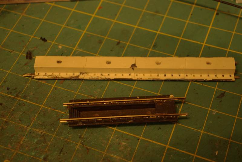
Couldnt get single lengths of Peco 83 over here but I was able to get lengths of MRE along with 100:83 transistion joiners. The site in Florida gave me the option of buying weathered track.
I was a little surprised when I opened the parcel:

Its basically track that is sprayed overall with some form of conductive paint……..locos run on this exactly as is……….I am rubbing it down a little with a peco eraser but more to tie in with the peco track………….the sleeper (tie over here) size and spacing make the difference very apparent………hopefully once ballasted it will not be quite so obvious.
The close up shows the insulated joiner which is an improvement on Peco.
This shows some of the roads set up on the TT…..you have to remove a couple of sleepers and file about 3/16" at the end down to an arrowhead

The calibration or indexing is a little laborious but once done is very consistent and the transition between bridge and service road hardly noticeable
So now all the TT service roads on the main board are set and wired

The bridge is off ( and disconnected!) while all the drilling is going on. The coal ramp has some formers in but thats a tale for another day.
The shots shows the six roads serving the round house and on the left an open siding that will probably serve the Sandhouse (Once I have found the photo Trevor!)
Each road is (or will be) 23" long and split into two isolated sections…….hence the gap…………..the roundhouse will be modified Scalescenes the walls of which are only 10" long……..I decided I preferred to have an open service road in front rather than double up the walls……not super realistic but I think it will be more attractive from a viewing aspect.
One issue I am wrestling with is ……inspection pits. They should really be on each of the service roads and then again in the shed itself………..I really dont fancy cutting 6 or even worse 12 slots and then chipping out all the sleepers. The service area will be infilled with concrete……I cant make up my mind whether to create faux pits by covering the sleepers with v thin card painted black or just leave well alone and pretend the pits are in the shed which will have a roof on any way…………in fairness at least half the roads will have locos most of the time……and there will be other detailing like lights and water cranes etc
Any thoughts or comments on this would be much appreciated…………………………
Posted

Inactive Member
Inside there are locos, LED lighting and someone welding.
It looks fine. :thumbs
Max
Port Elderley
Port Elderley
Posted
Full Member
I expect there's a reason why the TT lined up as shown above is not feeding the 'last' outlet to avoid the abyss.
As it stands there is room at the other side for an additional exit (but not in the 'covered' picture).
You will know best.
Also, I expect it is just a shadow but, where the TT is lined up with the exit there is an apparent misalignment (on the RH to view) which, if true, will cause problems.
Not criticisms - just observations which you will disregard as necessary of course.
Good stuff!
 Last edit: by ddolfelin
1 guest and 0 members have just viewed this.