Granby Junction 1948 N. Wales
Posted

Full Member
GWR/LMS OO Gauge DCC RR&Co
I didn't notice that until you pointed it out, John.No idea what the answer might be.
Have a lovely time on the boat.

Posted

Full Member
Thanks for the good wishes DDI didn't notice that until you pointed it out, John.
No idea what the answer might be.
Have a lovely time on the boat.
I am a little embarrassed about the shot to be honest……..like many of us, I suspect, I take a load of photos……load them on to the editor and then select the one or two I intend to use for the post then upload them
In this case I did all the above and was merrily typing away came to the point about the frame being out of line (which is actually very apparent) and realised that the shot I had selected, for other valid reasons, cunningly concealed the defect I was writing about!
I will almosr certainly leave it…….how long has that tower in Pisa been out of plumb?
Posted

Full Member
As a newbie here I was looking at other members layouts when my eye was drawn to the magic words 'GWR 1947'. Since this is to be the setting of my forthcoming 'Market Havering and Parmouth' layout I started reading at page 1 and after the best part of 2 days I finally reached page 34. By this time my jaw has dropped so far as to be virtually detached from the rest of my face and I am just sitting here in a state of total awe. :shock:
The amount of research that has gone into Granby and the level of detail incorporated into it are absolutely mind boggling. There are so many highly realistic dioramas within the layout that it is difficult to select any individual one above another though the ones that particularly stand out for me are the Canal Scene, the Turntable Facility and, of course, the latest Goods Yard & Warehousing area. I plan to have a canal and viaduct scene on my new layout so I shall certainly be referring back to your thread for inspiration. The little diorama of the single way traffic under a low railway bridge took be straight back to a virtually identical scene at Stubbins, which is just outside Ramsbottom in Lancashire. I can remember when my father used to fill up his Standard 8 there. Petrol was 2s-6d a gallon and he could "fill her up" for a Pound. Happy days. :lol:
As for the signalling - let's just say I will most definitely be coming to you for advice when I get to that on my own layout.
Thank you so much for sharing your layout build with us and I look forward to following its further progress with eager anticipation. :thumbs
 Last edit: by Chinahand
Regards,
Trevor
Trevor
Posted
Full Member
I left you with the goods yard module in place but not yet integrated into the layout
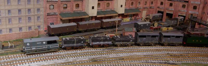
So the principal focus since I got back has been to fit the connecting lines, ballast, ash/grass the edges, fill the gaps in the backscene and finalise the signalling
Here is an overall view
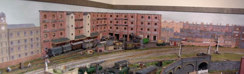
Next the right hand side with a repeat of the multilayer Townscene house backs that I used at the back of the fiddle yard
A close up of the Weigh Bridge Office…..somewhat modified
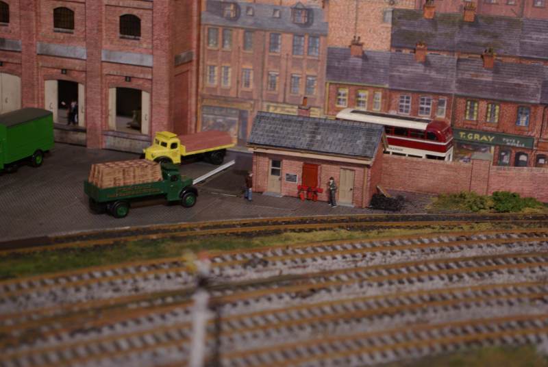
Modified…..previous shots showed a gents convenience attached to the office………..sadly this didnt survive contact with a shunted GWR fruit wagon. Maybe one day I will learn to check clearances more closely.
The dodgy bargeboard on the office was also a casualty!
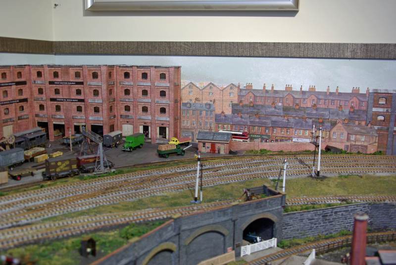
Here is the left hand side where I filled the gap with the 2 Townscene Mills cut and pasted to add another storey and next to that a dark brick Scalescene ultra low relief warehouse.
Given hindsight I should have reversed them because the light tones of the mill are too great a contrast between the two warehouses…….naturally I have used super super strong glue
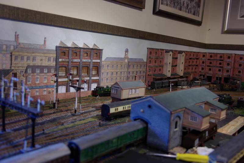
Heres a shot of the entrance to the goods yard with the main signal gantry back in place and finally in place the advanced starter and distant for the down slow line
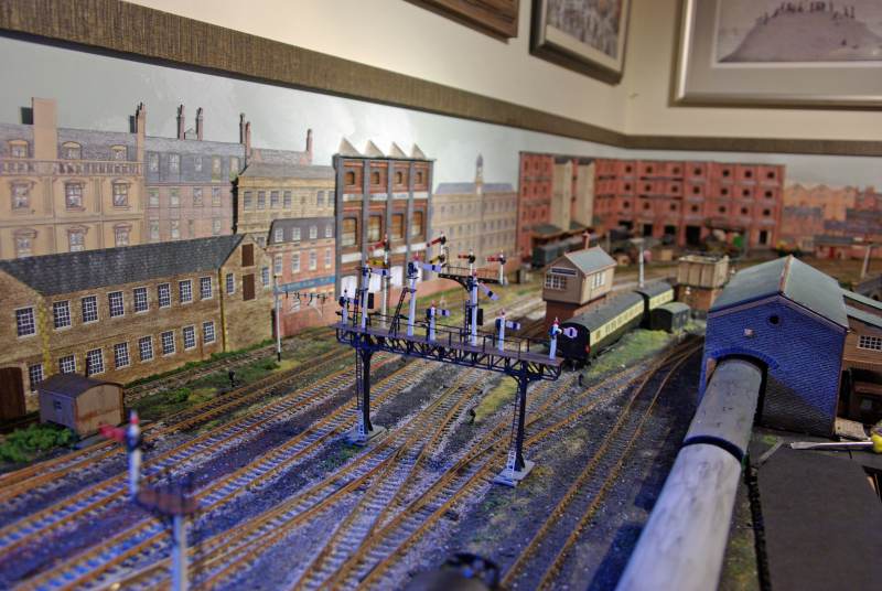
Loading gauge installed on entry exit road
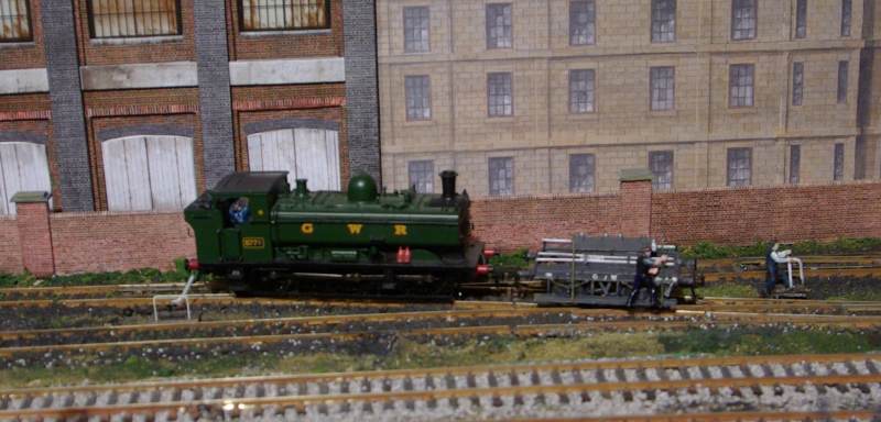
The loco loop with a 4-6-0 Manor waiting for the shunting of the Bristol-Birkenhead Fruit to fbe completed………you will see a lot more of this loco in my next post

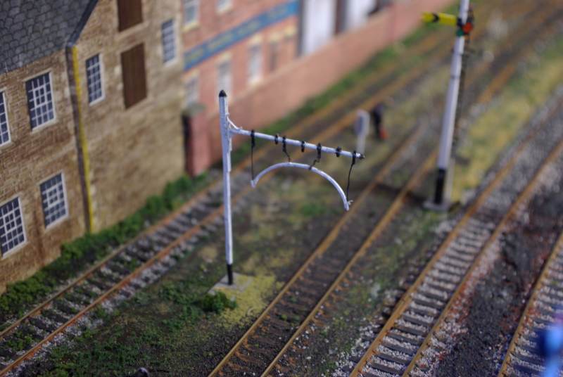
The main reason for posting now is to show the new position of the exit signal from the goods yard……going north from here the points to the loop are controlled from the main signal box by ground signals
Until this point

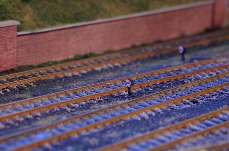
The Down slow to the right is controlled by the signal I talked about earlier……the lines to the left are controlled by the stop board

This was a standard sign at any reasonable sized GWR Yard……it would normally have been illluminated……all locos have to stop and can only proceed by hand signals…….points are shifted manually by levers
More about the shunters wagion next post
Posted
Full Member
Regards,
Trevor
Trevor
Posted

Full Member
I was going to reply earlier but spent too long studying the shots and ran out of time ……..:sad::sad:
Trevor has really summed it up. Granby is a magical place to be and such an inspiration to me, and, I'd guess, many others.
I love the way you've used the Townscene backdrops. They give an excellent 3D impression - perhaps the only thing that might improve it would be giving some shine on the slate rooves to prove it's always raining in Lancashire ………….:lol::lol:
It's impossible to pick out any single "scene" as being special - they're all so good. Looking at the overall shots, the railway blends into the industrial scene extremely well. So often one sees some buildings plonked around a layout to give it a sort of "artificial" raison-d'etre. Granby is a copy of what was actually there and with so many interesting and highly detailed cameos you can almost hear the activity. :thumbs:thumbs
Sailing over there must be extremely good to drag you away from your dark satanic mills for so long …………….:cheers:cheers
'Petermac
Posted
Full Member
I have always liked the Townscene kits…..he actually has some country side sheets with some quite good transitions to the townscapes……there is a port scene as well. It is a bit of a pain to cut out all the chimney pots and church spires etc…….I glue them to card before cutting out……paint out the cut edges……brace them to prevent warping then fit spacers of different thicknesses to suggest depth
It is supposed to North Wales, Peter, although it was probably even wetter there. I am afraid you have detected Granby's major design flaw……..it does look far more how I recall Oldham and Rochdale than Wrexham! But the nearest the GWR got to Lancashire would be Warrington and it is too complicated now to re write the legend!
The sailing here is brilliant……one of the worlds best kept secrets…..its truly Sea to Sky Country
I have spent the last week running trains……now there is a novel concept!
 More specifically I have been trying to perfect the first shunting sequence for the yard……it involves about 14 seperate moves…….almost done but I have had a lot of trials and tribulations…..track….rolling stock….RR&Co you name it I have found it
 …….I hope to post a video but never having done one before it may take a while…………….I will try and post some photos showing the sequence and describing some of the issues/solutions shortly
Posted

Full Member
Doug
'You may share the labours of the great, but you will not share the spoil…' Aesop's Fables
"Beer is proof that God loves us and wants us to be happy" - Benjamin Franklin
In the land of the slap-dash and implausible, mediocrity is king
"Beer is proof that God loves us and wants us to be happy" - Benjamin Franklin
In the land of the slap-dash and implausible, mediocrity is king
Posted
Full Member
I suppose I don't associate north Wales with industry - far too close to Cheshire for anything "dirty" …………:roll::roll::roll::lol::lol:
South Wales - yes but North Wales is Conway and Llandudno, Snowdonia and Colwyn Bay. The GWR theme ought to have been a clue but you're absolutely right, the scene could equally be a Lancashire Mill town - particularly the canal area although canals are canals I suppose.
'Petermac
Posted
Full Member
http://www.youtube.com/watch?v=ccjm47Sh3LU&feature=plcp
The big lesson I learned from this exercise had little or nothing to do with computor control……the biggest challenges related to smooth consistent running and uncoupling rolling stock. I learned at first hand the importance of accurately fitting Kadee couplers to older stock. Most of the activity involves the stock being pushed rather than pulled over a series of points……inconsistent stock weight resulted all too often in derailing……I should have videoed or at least photoed the more spectacular pile ups.
The shunting loco…..a Bachmann 57xx (big surprise) with a Lenz Standard performed impeccably……..the jerky speeds were due to me adjusting the schedules to cope with some poor trackwork


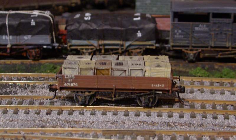
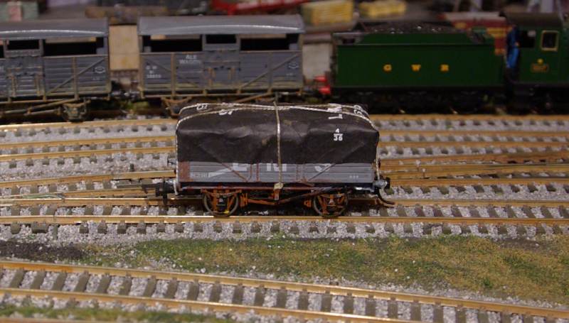
The shunters truck was a quintessential component of GWR operation. I was determined to have one operating. The model that I showed earlier (my first kit circa 1992) was not really fit for purpose so I bought another kit from Cornwall and rebuilt the chassis……..and attached a phenomenal amount of lead wherever I could find space

Kadee coupler at the business end and tension lock to the loco to avoid inadvertent uncoupling……I know its a little unrealistic having the shunter glued (literally!) to the running board during the entire operation but I love the contrast between then and now in terms of elf'n safety.
The brake van I used is one that Richard (Wheeltapper) obtained for me so it is kind of special.

Some light weathering and a tail lamp otherwise straight out of the box.
Underneath……its a little different
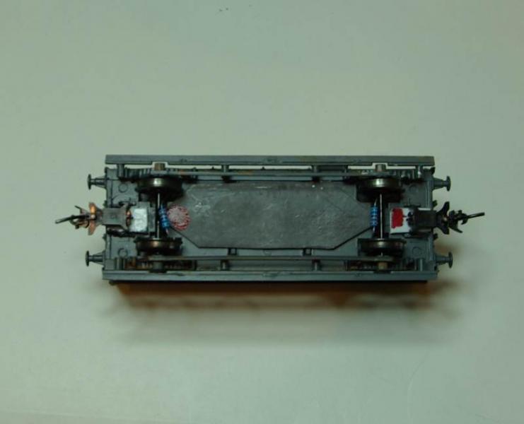
Great lump of lead….cut back to avoid binding on the wheels…….dont ask
Kadee couplers in NEMS pockets………huge plus……it means when I want a fixed rake I can just switch back to tension locks……….save money and avoid unplanned uncoupling.
I found a lot of derailments were caused by the old style Tension Locks and wherever possible these have been removed
Having a standard height for the Kadee is absolutely critical……..any variation more than 1 or 2 mm causes problems……either fouling magnets/shorting points (too low) or unplanned uncoupling (too high)
The white shims which enable me to get a precise height are cut from the clips you get on sliced bread. I owe Ron (Sol) a six pack for that tip
The blue things on the axles are 5k resistors
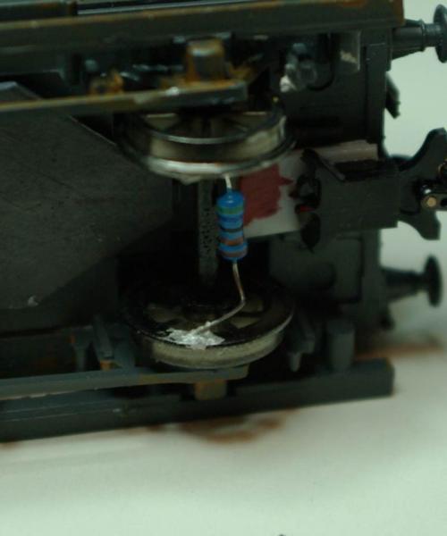
Without going into too much detail, an RR&Co layout is split into electrically isolated blocks……like the real thing. It plots the movement of a train by capturing the current draw as it moves from block to block………..once a block is empty ie no current draw it is released for the next train………not a good idea with a long train………………loco leaves the block but wagons are still transitting. The answer is to fit a resistor across
the wheels…..the minimal draw is sufficient to be captured and thus show the block as still occupied
The rolling stock is set up in rakes of 5 wagons…….the magic number being that which will fit into the runaround loop at the Cynwyd branch.
The plan is to constantly interchange them using variants of the shunting routine. A 15 wagon train will come from Birkenhead (storage) or the south (storage other end)…….5 will be dropped at Granby and 5 picked up. A 5 wagon train will go down the branch and come back with 5 different wagons (typically a rake of 2 and one of 3 ) and so on
I am astonished (and somewhat embarrassed) at just how much rolling stock I have "collected" over the past 20 years. A combination of RTR and indifferent kit built…….its weathered and generally loaded with some form of freight
Getting it up to an acceptable running and coupling standard has taken rather longer than I expected……hence my indifferent posting record.
Its not really the most exciting subject so I hope this hasnt been too boring.
Next time I will try and show that I run some locos that are not Panniers!
Posted

Full Member
Is the resistor just soldered to the two wheels John?
The blue things on the axles are 5k resistors
Without going into too much detail, an RR&Co layout is split into electrically isolated blocks……like the real thing. It plots the movement of a train by capturing the current draw as it moves from block to block………..once a block is empty ie no current draw it is released for the next train………not a good idea with a long train………………loco leaves the block but wagons are still transitting. The answer is to fit a resistor across
the wheels…..the minimal draw is sufficient to be captured and thus show the block as still occupied
I tried micro resistors with conducting ink ( you literally draw it on) but had little success as the pesky devils are so small. Your method looks like it is a much more suitable approach for my fat fingers

Just because you have a loco other than a pannier running doesn't preclude you having a pannier in the background;-)Next time I will try and show that I run some locos that are not Panniers!
PS John - your posts are never boring
Posted
Full Member
PS John - your posts are never boring
Well said, Dave….
Encore!
Doug
'You may share the labours of the great, but you will not share the spoil…' Aesop's Fables
"Beer is proof that God loves us and wants us to be happy" - Benjamin Franklin
In the land of the slap-dash and implausible, mediocrity is king
"Beer is proof that God loves us and wants us to be happy" - Benjamin Franklin
In the land of the slap-dash and implausible, mediocrity is king
Posted
Full Member
[user=540]gdaysydney[/user] wrote:
I glue the resistor to the axle with superglue and make the connection to the wheel like you with silver conductive paint……I dont draw it so much as daub it I am afraid!Is the resistor just soldered to the two wheels John?
I tried micro resistors with conducting ink ( you literally draw it on) but had little success as the pesky devils are so small. Your method looks like it is a much more suitable approach for my fat fingers
The new Coupling pockets on Hornby, Dapol and some Bachmann make this impossible/difficult without the resistor fouling the body…….so I have to glue the resistor to the body and hook the arms around the axle relying on friction to make the contact……not ideal and not 100% effective…..but as long as I have current draw every 12" or so there is no problem from a protection point of view.
Its rather different when you are pushing a rake into a siding block……if you use tail of train (ie the loco) to activate the stop marker you are increasing the distance that TC will be computing so using head of train (ie lead wagon) is much more accurate…………so the resistive wheel set has to work 100% on that wagon!
" Next time I will try and show that I run some locos that are not Panniers! " Just because you have a loco other than a pannier running doesn't preclude you having a pannier in the background;-)

Posted
Full Member
Posted

Site staff
The new Coupling pockets on Hornby, Dapol and some Bachmann make this impossible/difficult without the resistor fouling the body
perhaps John, these may help
http://www.dccconcepts.com/index_files/DCCflickerfree.htm#Pickup Spring
Last edit: by Sol
Ron
NCE DCC ; 00 scale UK outline.
NCE DCC ; 00 scale UK outline.
Posted
Full Member
Not sure about flicker free I just need to mount a resistor on the axle …..the problem is that that the mounting device for the NEMS pocket extends under the axle thus reducing the clearance
PS Hope you saw the Thank you about the shims……I owe you a beer or two:thumbs
Posted
Site staff
Shims are one of the things that mounting Kadees onto UK stock, is a fact of life.
Ron
NCE DCC ; 00 scale UK outline.
NCE DCC ; 00 scale UK outline.
Posted
Full Member
I'll bet that shunter's left knee will give him some gyp when he's older ………………:roll:
It took my small brain some time to realise why that little resistor didn't wind itself around the axle (:oops:) - a neat solution to your "power flow" problem.
You are absolutely right about wagons, particularly kit built ones, being too light. I'm not at the stage of "testing" in earnest just yet but when I get there, lead sales in France will go through the roof. When you compare the weight of today's plastic offerings - brilliantly detailed as they are - with the likes of Wrenn with their die-cast chassis some years ago, you get quite a surprise. I think it was Sol who has a formula for the correct length to weight ratio for wagons……….. :hmm
I need (or rather "want") to change to Kadees - they do look much better and, even using the hand of God, are so much easier to couple/uncouple than TL's but our bread no longer uses those wonderful plastic closures. Ours are a piece of metal reinforced "crimp" tape. Maybe a piece of stale crust from a baguette would do the job just as well. It's certainly very good at pulling teeth …………:roll::roll::roll:
'Petermac
Posted
Full Member
:oops::oops::oops:…….bit slow there Ron….my apologies. Thats a great reminder actually because I was planning to build springs like that to add pick ups to an Autocoach and my tiny mind hadnt made the lateral connection to the resistor issueJohn, not so much flicker free but pick up springs which go around the axles.
Shims are one of the things that mounting Kadees onto UK stock, is a fact of life.
Petermac wrote:
Thanks Peter glad you liked it. You are so right about Kadees……my storage yards are are far too tight anyway but the ability to lift a wagon or carriage vertically out of a rake without twisting and derailing 4 others is a big advantage. Purists will argue that unlike carriages, they are very unprotototypical for wagons. But anything less prototypical than the earlier Dodgem type Tension locks I have yet to see!I need (or rather "want") to change to Kadees - they do look much better and, even using the hand of God, are so much easier to couple/uncouple than TL's but our bread no longer uses those wonderful plastic closures. Ours are a piece of metal reinforced "crimp" tape. Maybe a piece of stale crust from a baguette would do the job just as well. It's certainly very good at pulling teeth …………:roll::roll::roll:
I tried for a long time on Granby II with Tension locks and Ramps but finally made the changeover……not cheap, time consuming and, in my case, not always secure or correct first time………….but spread over time well worth it not only in terms of reliable coupling and uncoupling but also better running.
A baguette crust may work with a sharp scalpel blade and superglue:lol:
Posted
Site staff
. I think it was Sol who has a formula for the correct length to weight ratio for wagons……….. :hmm
I use this
http://www.nmra.org/standards/sandrp/rp-20_1.html use Ho or Sn3 recommendations.
and there is this from Down Under
http://www.amra.asn.au/massstandard.pdf
Ron
NCE DCC ; 00 scale UK outline.
NCE DCC ; 00 scale UK outline.
1 guest and 0 members have just viewed this.