Granby Junction 1948 N. Wales
Posted
Full Member
GWR/LMS OO Gauge DCC RR&Co
Me neither.
Cheers Pete.

Posted

Full Member
They are by no means perfect. Some of the close ups expose the imperfections rather cruelly.
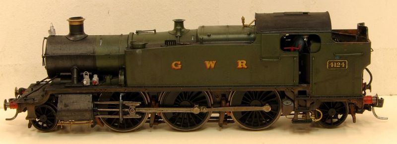
However, once the 3' rule is invoked I think they will pass as reasonable facsimiles of hard working locomotives in1947
Modelu lamps are great……with the slot already in the base, fitting them to the lamp irons is a breeze.

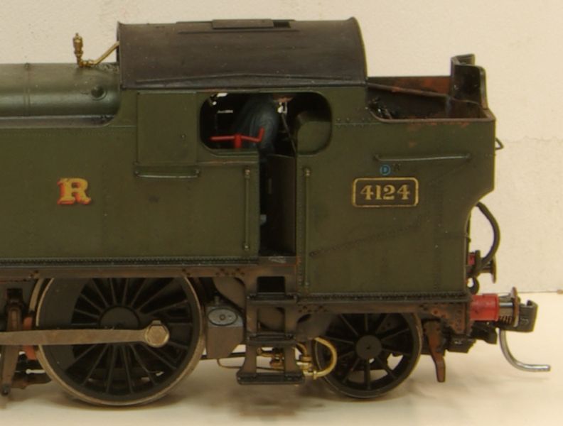
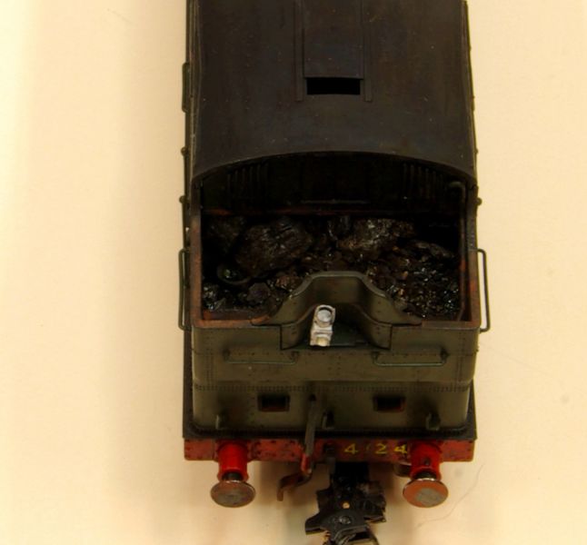
The crew are in now place…..not without incident……as the the bent reversing screw handle demonstrates.
The camera is very useful in highlighting other previously undetected errors……..like the sand pipe for example (since corrected and now pointing the correct way!)
The pipes are quite delicate….two snapped off and had to be replace with brass wire bent to shape.
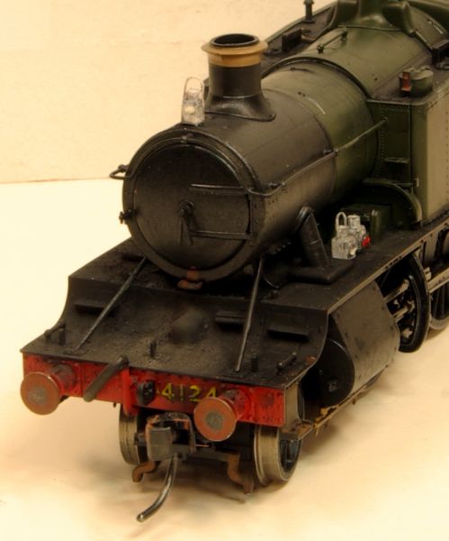

The usual dilemma with head lamps….. front and back on at the same time! These locos will be running an intensive commutor service with rapid turnarounds. On balance, I prefer to always run with the correct head code and blame the fireman for not removing the one at the rear.
Time for them to start earning some revenue:
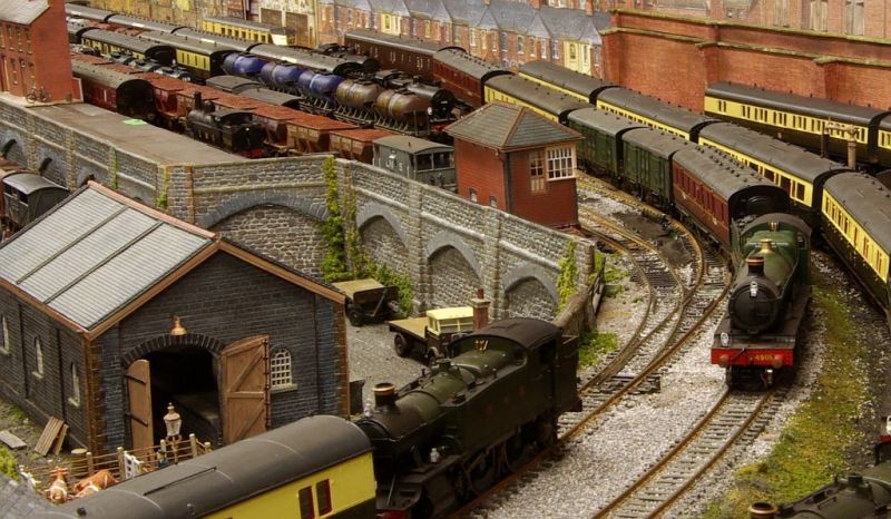
Here we see 4124 and a 4 car D Set with a suburban passenger service from Birkenhead Woodside
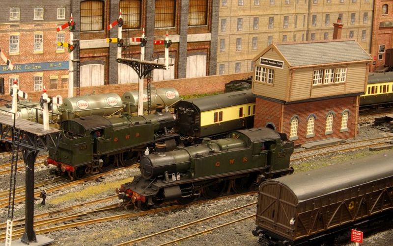
4121 is already simmering in the relief road in readiness for the return to Birkenhead.
I must confess this is a a somewhat posed shot…..Locos normally enter Granby chimney leading…..its a decade old convention….but I wanted a front and back shot.
Routines like this, involving a loco exchange at both ends, need 3 locos. Right now I am using a 56xx 0-6-2T to make up the numbers…………hopefully the Dapol Mogul, due next month, will give some indication of what we can expect from their Prairie…….but how long do I wait
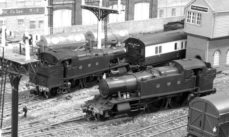
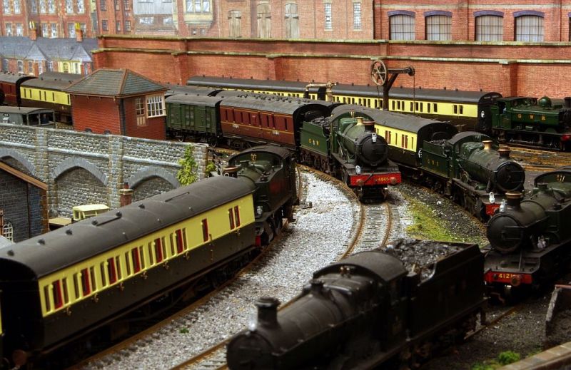
Here is a black and white shot to finish which captures, quite nicely, the look I was aiming for.
Best Wishes from Vancouver
John
Posted

Full Member
Michael
Posted
Full Member
Cheers Pete.
Posted
Full Member
I am amazed at both your speed and stamina Michael. :lol:…… your reply came so fast I had hardly time to put my pen down (metaphorically speaking) …….more to the point at 17.15 local time that translates to 1.15 am in the UK unless you have taken the hour off already even so its still after midnight……….long past my bed time! :roll:
Glad you approve of my lamp philosophy……it actually gets worse because I insist on tail lamps on the rear coaches so they also get duplicated :oops:
Will your Southern locos be carrying discs? Out of interest do they duplicate or replace Head Lamps as class indicators……or are they in fact route indicators? I have always meant to ask.
Best Wishes
John
Posted
Full Member
As to timing, normally well passed my bedtime too ,but I was still working, so I got the email alert of your post. And I'm always intrigued by your updates, so had to check it out!
Michael
Posted
Full Member
The exit road consists of a five turnout ladder
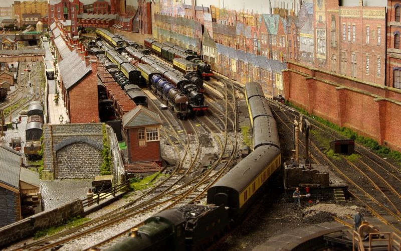
The storage yard and branch line were the first boards I wired up back in 2008. Electro-frog points powered by Peco twin solenoid motors with frog polarity switched by Peco switches! A veritable museum piece for such a high traffic area which has caused me more grief over the years than any other part of the layout.
The contrast with the the rest of the layout (Tortoises) could not be more marked.
Over time I found the Peco switches unreliable and some actually failed. To solve the problem I bought some of the then newly introduced DCC Concepts ADFSX units which acted as both decoders and polarity switches.
In many ways these units solved the problem. The downside for the intial releases, like mine, was that when the power was disconnected,short or switch reason, the device reverted to the default polarity regardless of the actual turnout position! There were work arounds but it was clearly less than ideal!
Earlier this year I needed switches for two newly installed surface mounted motors. DCC Concepts were out of stock of their devices and I stumbled across this self latching relay :
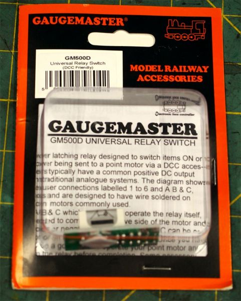
Its a very simple and inexpensive relay switch…….no decoder or CDU like the DCC Concepts unit but a fraction of the price
I suspect someone with a knowledge of electronics could knock these up for cents. But I know my limitations!
Here it is wired up:
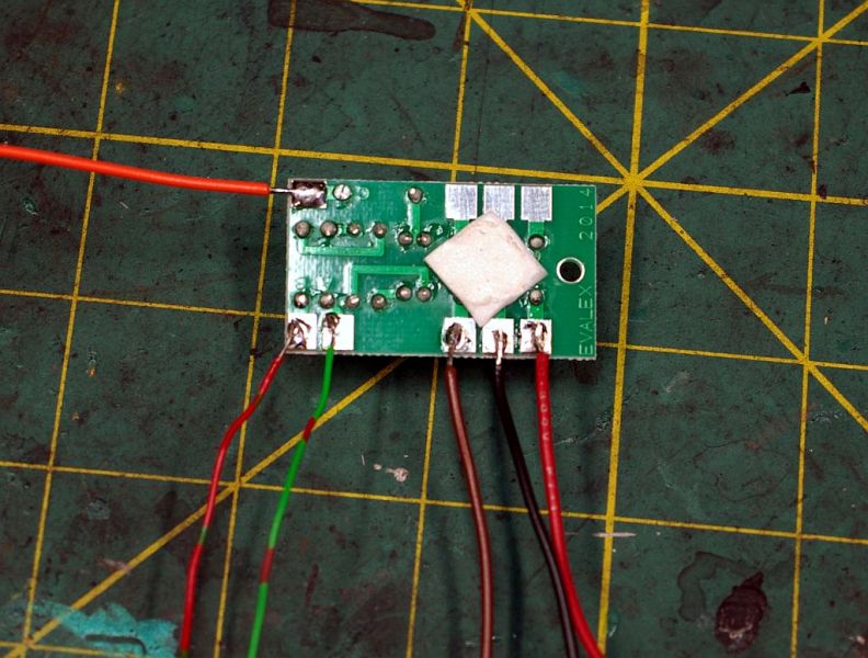
Bottom right clock wise:
Red DCC Bus +ve
Black DCC Bus Common
Brown Frog Feed…………this is the only wire that has to be connected directly to the turnout
Green/Red Point Motor
Red/Green "
Orange Point Motor Common
The three unused solder pads are for accessories….signals or switch board LEDS
Here are two in place on the edge of the baseboard

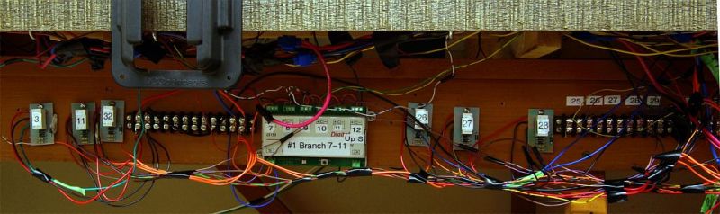
Here is a shot of the sub-assembly that controls the storage turntable and associated sidings
Apart from demonstrating its an urban myth that you only need two wires for DCC, it hopefully shows how easy the relays are to install

Turnouts 85 and 86 are 6' away at the very back of the baseboard. The only wire that had to be fed directly to the turnout was the brown frog feed.
The DCC contacts and Point Common were fed to the chocblock for the sub assembly about 2' feet away (just in the picture extreme right)
The point motor wires from the relay joined the matching wires from the motor already in place in the point decoder (seen at the right…..#2 Storage 85-91) If I used switch panels rather than decoders they would have been fed to the switch.
For anyone interested, the 5 units between the two Relays and the LS150 Point Decoder are occupancy detectors for 8 blocks in the turntable area……not part of this tale
Testing the relays was super easy……rather than leaning across the baseboard, displacing more chimneys,lamp posts etc, and trying to connect and read a multimeter while switching the turnout ……….I connected everything up except the frog feed. From the comfort of an armchair I was able to connect the multimeter to the frog dropper (brown wire from the the relay) and the Red DCC Bus…….throw the point……if I get a reading and the frog in the resultant position should be Black…GOOD NEWS……connect the meter to the Black bus, throw the point and check again.
If the polarity is being switched incorrectly Black when it should be Red simply changeover the point wires from the relay. I guess you could re solder them….I just changed them over in the decoder…….Job done
I am not suggesting that these relays should be used when starting a layout but they are a very effective band aid for effecting repairs or add ons………particularly for elderly modellers with bad backs and poor eye sight
Here are six more units……three of which have solved my ladder problemj
Note……..there are similar relays designed for DC units………. GM 500
For DCC layouts you must use GM500D relays. GM500 without the D do not work. How do I know this? I have six such relays looking for a good home!
Regards from Vancouver
Posted

Site staff
I have found that at times especially with side mounted solenoids, I had LEDS worked by the operating toggle but the solenoid did not move so trains derailed, I fixed it by adding a microswitch to the tiebar for the LED switching. Frog switching - I used frog Juicers from Tam Valley
Ron
NCE DCC ; 00 scale UK outline.
NCE DCC ; 00 scale UK outline.
Posted
Full Member
Cheers Pete.
Posted

Full Member
Pleased you sorted the electrical problems, they're often an absolute nightmare. Certainly they are for me, particularly when it comes to electronics. As you may remember, I too have used these Gaugemaster relays (I didn't know that's what they were called until you said - I called them polarity switchers ! :oops:) and they really are little gems, and not too expensive either.
I'm half way through replacing my dead frog points with live frog and in some cases, surface mounted motors are my only option (because of existing sub framing under the baseboards). These gadgets have been an absolute life saver for me. I do have a frog juicer in stock Sol but had planned to use that elsewhere.
I know the "normal" GM500 won't work on DCC but I wonder if the reverse is also the case - will the GM500D work on DC systems ?
It does rather worry me in that all these systems work by detecting a short circuit, albeit very, very quickly, but I'd also understood that shorts and DCC, particularly with sound, are like water and electricity - they should be kept well apart ! I wonder if there will be any long term damage as a result of constant shorting ………………. If the damage only becomes evident after 15 or 20 years, then I don't care !!
'Petermac
Posted

Full Member

 Last edit: by
Posted
Full Member
Some more great shots of the layout there John - I could look at those all day long………………..and probably will !!
Pleased you sorted the electrical problems, they're often an absolute nightmare. Certainly they are for me, particularly when it comes to electronics. As you may remember, I too have used these Gaugemaster relays (I didn't know that's what they were called until you said - I called them polarity switchers ! :oops:) and they really are little gems, and not too expensive either.
I'm half way through replacing my dead frog points with live frog and in some cases, surface mounted motors are my only option (because of existing sub framing under the baseboards). These gadgets have been an absolute life saver for me. I do have a frog juicer in stock Sol but had planned to use that elsewhere.
I know the "normal" GM500 won't work on DCC but I wonder if the reverse is also the case - will the GM500D work on DC systems ?
It does rather worry me in that all these systems work by detecting a short circuit, albeit very, very quickly, but I'd also understood that shorts and DCC, particularly with sound, are like water and electricity - they should be kept well apart ! I wonder if there will be any long term damage as a result of constant shorting ………………. If the damage only becomes evident after 15 or 20 years, then I don't care !!
It's said that some decoders can be affected/damaged by short circuits. I don't think it's the actual short, but the voltage spike when the juice is restored. If this is the case and you want a belt and bracers approach you can easily make a little device that soaks up the spike rendering it harmless. It goes by various names eg: snubber, damper etc. It simply consists of a ceramic capacitor and a resistor. If you want the values I'd be glad to dig them out and post them here.
Cheers Pete.
Posted
Full Member
Always try to look on the bright side of life!
Barney
Barney
Posted
Full Member
Heathcote http://www.heathcote-electronics.co.uk/point_indicator.html do a similar unit that connects across the coils, for LED/Frog switching.
I have found that at times especially with side mounted solenoids, I had LEDS worked by the operating toggle but the solenoid did not move so trains derailed, I fixed it by adding a microswitch to the tiebar for the LED switching. Frog switching - I used frog Juicers from Tam Valley
Thanks Ron
I wish I had known about these devices a few years ago……would have saved a lot of aggro.
Best Wishes
John
Posted
Full Member
peterm wrote:
Yep two wires… I don't know where you get all that other stuff from John. ;-) :)
 You would be surprised how often I ask myself that!
Posted
Full Member
When I decided to build a layout, I was seduced by the two wire philosophy of DCC, hahahaha! I've come to accept it is a bit like buying some brands of car - there is a basic system, but once you start wanting any extras, the complexity - and cost - soon mounts. But it keeps the grey cells busy, I suppose.
Michael
Posted
Full Member
On reflection I think I got the idea of using these relays from you! My belated thanks for an excellent suggesion
I dont know for sure but I suspect the 500D would not work with a non DCC layout.The GM500 is designed solely for AC whereas the GM 500D has circuits to handle DC and AC.
I have never used frog juicers……although they attract plenty of favourable comments I am a bit wary of them…..I create enough accidental shorts without doing it deliberately! :lol:
Best wishes
Posted
Full Member
Electrics on the layout is one of the things I find difficult to fathom out. I've done it before so to me it's a matter of trial and error! I have to say I do admire your wiring John.
Thanks Barney……you are very kind but I only photoed the "neat" bits! :shock:
Best Wishes
Posted
Full Member
Hi MichaelWhen I decided to build a layout, I was seduced by the two wire philosophy of DCC, hahahaha! I've come to accept it is a bit like buying some brands of car - there is a basic system, but once you start wanting any extras, the complexity - and cost - soon mounts. But it keeps the grey cells busy, I suppose.
Michael
Thats an excellent comparison
If you strip out optional extras like occupancy detection and turnout control then DCC layout wiring is literally two wires…..my Red and Black……connected to the track by short lengths of identically coloured wire. No different from a basic DC layout. It is actually simpler because with DCC you can, at the same time, run more than one loco on the layout at different speeds and in opposite directions without any additional wiring (I accept there is the additional cost of decoders). It is worth remembering that to run just one loco and have a second stationary loco on a DC layout means there has to be a switched isolated section for the parked loco.
My apologies for preaching to the converted :lol:
Best wishes
Posted
Full Member
Always try to look on the bright side of life!
Barney
Barney
1 guest and 0 members have just viewed this.