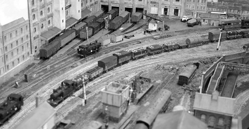
Granby Junction 1948 N. Wales
Posted

Full Member
GWR/LMS OO Gauge DCC RR&Co
[user=1886]DaveH_Murcia[/user] wrote:My apologies Dave. Until I checked I hadnt appreciated that Cobalt I P motors actually had a built in decoder. That must save a load of wiring. However they should not lose their memory like that…..it must be incredibly frustrating particularly when running with TC. As Nigel said, I would hope DCC Concepts are addressing the issue.Hi John. Don't want to hijack your area but basically a short caused by a train or rolling stock at pointwork (which hopefully should reduce anyway as I change old, bad back to back wheels) causes DCC Concepts Cobalt IP point motors to loose there programming. It is usually the same ones. I will get some PSX units anyway and start the minor (hopefully) rewire.
Best Wishes
John

Posted

Full Member
I did a bit of reading (and learning!) on this. As I understand it: Small decoders (read cheap function only decoders) do not have the same short protection that is found in larger (more expensive) decoders, they typically use something called a zener diode, and have limited ability to mediate voltage spikes that will occur during a short. That will apparently scramble any programing. The idea of any short protection in a decoder is to control the voltage spike from damaging the electronic components until the power unit switches off. I doubt whether a PSX will actually have any effect, as it is primarily there to shut down a power district.
Dave, is your system shutting down during these shorts? I would contact Richard Johnson at DCCconcepts and ask some questions.
Nigel
©Nigel C. Phillips
Posted

Full Member
How is it going with the Dapol 14xx John?
Michael
Posted
Full Member
Hi MichaelHow is it going with the Dapol 14xx John?
Michael
Thanks for the interest……its gone very well…..so much so that I am attempting a second! Just need to take a couple more photos and do some fiddly detail and the first one is already to go
Cheers
John
Posted
Full Member

14xx 0-4-2T the quintessential GWR branchline loco…..
Unfortunately, until recently, the only RTR loco available was the ex Airfix Hornby/Dapol version
I have always found them to be unreliable runners and I hate the traction tyres. I did eventually get two running ok but only as a result of permanently coupling them to Autocoaches, to which I had added pickups and wired in enormous Stay Alives.
When the DJM/Hattons locos were released, the Dapol locos disappeared, with a sigh of relief, into the graveyard drawer to join other failures. One of which was my first and only attempt to build a loco chassis. This doomed effort proved conclusively how wise I was not to attempt a career in Engineering……far better to focus on Women's fashion……..I have no problem determining the best shade of Green for a loco!
I was probably a bit premature in celebrating the DJM release but with the aid of Zimo decoders and SA they now do regular automated runs on Granby.
Ever since, the Dapol locos have sat in the graveyard drawer, gathering dust; waiting for me to pluck up courage to replace the traction tired driving wheel set.

I guess there was some margin of error in that I had four available sets to work with!
The actual wheel replacement was actually much easier than I had imagined
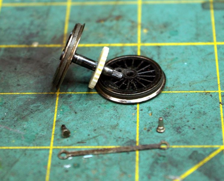
The connecting rod retaining pin is just a push fit easily prised clear with a screwdriver. The wheel itself is also a push fit on the serrated stub of the axle.
I am getting a little ahead of myself because first the body had to be removed followed by the keeper plate:
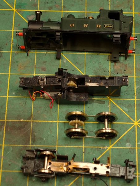
And there you have it …..the basic components of the 14xx
For some bizarre reason I was reminded of my Army days…..stripping and assembling a Sten Gun…..and being surprised at how an effective device could be made up of so few parts.
Not sure about the Sten nowadays but by the time I finished the project I had definitely become an expert in stripping and assembling the 14xx
The paint scraped off the body is an essential part of the design. Somewhat to my surprise the chassis is live. The etched collector plate is protected by a layer of plastic
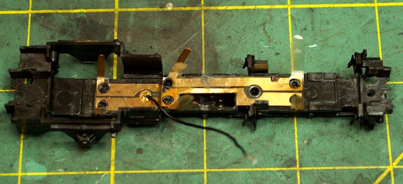 .
.Top right on the plate you can see a slightly raised tab which is unprotected……this contacts the exposed surface of the body and provides the left hand pick up. The RH being via the black wire (no colour coding in those days)
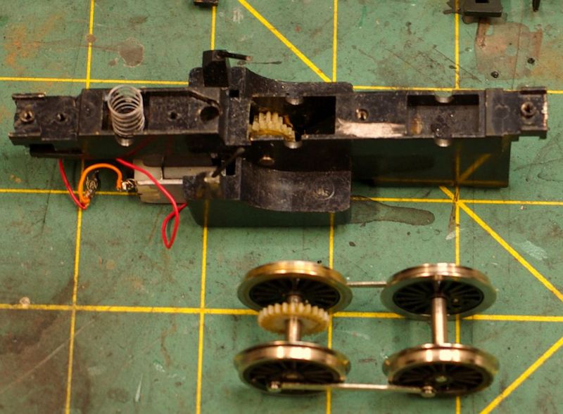
There are actually pick ups on all three wheel sets which I hadnt appreciated. The pick ups are protected on the inside by the plastic interface and are a right pain when trying to replace the keeper plate. Almost inevitably one protective strip becomes misplaced/jammed and it was not uncommon for a pick up to become similarly mis-shapen. In fact the LH Front pick up above succumbed to metal fatigue and I had to substitute a different keeper plate from the "spares " box
Once the tired wheels had been replaced, everything except the body was reassembled for testing on my rudimentary DC test track
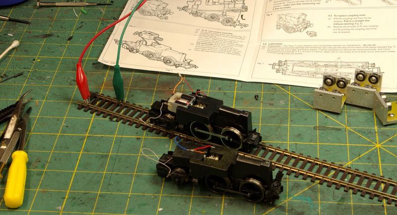
Electrically I had no issues……… everything went smoothly. Mechanically it was a different story. I understand the basic concept of quartering (I think) but never having done it before and having no tools ( I assume there is some device?) it all had to be done by eye……..ie trial and error…….lots of stripping and re assembling….hence my new found expertise!
Finally I got it sorted and was pleasantly supplied at how smoothly it ran……….time to add a decoder:
Unfortunately I then got a little ahead of myself……I fitted a Zimo MX617 and found room in the bunker for a 6700 u/f Supercap…..same configuration I now have in all my Panniers……checked everything on the programming track and the performance was absolutely stunning. Body back on…..crew in (legs intact) and off running on the layout………..but forgot to take any photos!
So in view of that success here is a photo of a second converted loco (why not…. I have enough spares!)

You may have wondered why there was a second loco in the DC test photo……..here it is ……all done with decoder fitted and blue and grey wires waiting for a Supercap from Youchoos.
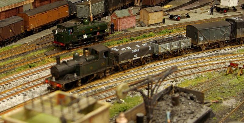
When I started on this exercise I wasnt really expecting much. At best, hooked up to an autocoach out and back or perhaps, a horse box roundy roundy, neither involving any uncoupling. In fact the loco performs with more accuracy and at lower speeds than the better of my two DJM 14xx. Visually, of course, its not in quite the same league although I have attempted to make some improvements to the exterior :
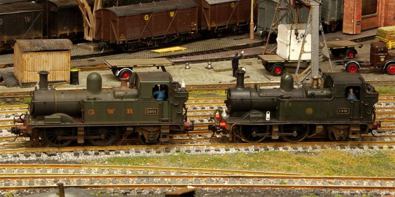
She is still looks a bit clunky but will definitely pass muster as an ultra reliable RR&Co layout loco. Now I have to decide where best to employ her.
I think I need to make a quick video to prove that all this adulation is justified.
Regards from a very happy camper in Vancouver
John
 Last edit: by John Dew
Posted

Full Member
The Dapol seems to be much the same as the 2008 Hornby I worked on.
Just a couple of points that I noted; the insulating plastic between the pickups and keeper plate extends behind the wipers to protect them from contact with the metal chassis. Mine were brittle or already missing and I removed the remainder, replacing with very thin off-cuts of PET from old packaging which I glued to the chassis core to prevent shorts.
Regarding the numbering of your second loco, according to the BR Database the Class 48xx were renumbered to 14xx in 1945-6 when the 48xx series numbers were required elsewhere (Class 28xx rebuilds) so 1401 with a shirt-button logo is out of period. Logo change to finish off perhaps as GWR came in from 1942? I have a similar problem with my K's kit 14xx when I finally get to rebuild it.
Regards,
Colin
Posted
Full Member
Great to see two locos that were once in the drawer now ready to be run on the layout and looking good witht he detailing. It's amazing how the addition of crew adds to the realism - something I have not got around to yet but will make a priority.
Michael
Posted
Full Member
Thanks Colin glad you like it. I mentioned in my last post that your thread was the catalyst that got me started…….. without your post I would probably have continued to prevaricate.Nice work John,
The Dapol seems to be much the same as the 2008 Hornby I worked on.
I think they are pretty much identical……I think I had one Hornby loco in the graveyard and may have use a part from it. Not sure but I think Dapol sold the tooling to Hornby
Just a couple of points that I noted; the insulating plastic between the pickups and keeper plate extends behind the wipers to protect them from contact with the metal chassis. Mine were brittle or already missing and I removed the remainder, replacing with very thin off-cuts of PET from old packaging which I glued to the chassis core to prevent shorts.
Thats a good idea…….wish I had thought of it.
I actually chose that body deliberately. Lots of locos lingered on to nationalisation and beyond with shirt buttons and even Great Western and I only have one or two.Regarding the numbering of your second loco, according to the BR Database the Class 48xx were renumbered to 14xx in 1945-6 when the 48xx series numbers were required elsewhere (Class 28xx rebuilds) so 1401 with a shirt-button logo is out of period. Logo change to finish off perhaps as GWR came in from 1942? I have a similar problem with my K's kit 14xx when I finally get to rebuild it.
Unless I find a photo of 1401 with "GWR" livery I dont think there is a problem. Some years ago I checked with the experts in the other place. The consensus was that the number plates were sent (from Swindon?) to local sheds and the change took place immediately in 1946……which makes sense. I wonder if the parsimonious GWR had the 75 old ones sent back to Swindon for re use on the converted 28xx………mind you they only needed 12!
Livery changes, on the other hand, were not immediate. They took place when the loco went in for a general overhaul (normally every 5-7 years). 1401 was built in 1932 so would have been out shopped in "Great Western"………..some time prior to WWII it would have received the Shirt button. With WWII intervening its quite feasible that a humble branch locio would continue like that until re liveried with the BR early emblem……..hence the heavy weathering.
I rest my case M'lud! :lol:
Best wishes
John
Posted
Full Member
Thanks MichaelA great "how to" John, although you will have to explain "quartering" to me! And the whole electrical bit is still a bit of a mystery to me… I understand the very basic principles, but as soon as I see terms like "live chassis" my brain becomes fuzzy.
Great to see two locos that were once in the drawer now ready to be run on the layout and looking good witht he detailing. It's amazing how the addition of crew adds to the realism - something I have not got around to yet but will make a priority.
Michael
Explaining the principles of quartering is beyond my capabilities. However a simple demo may help. Stop a loco so that the connecting rod retaining pin is at precisely 12 o'clock on one side. The pin on the other side should be at either 3 o'clock or 9 o'clock. If it is not it is unlikely the loco will run smoothly………I discovered this phenomena when I inserted both replacement wheels on to the axle at 12'oclock…….the loco ran like a demented kangaroo!
Similarly I dont really understand the principles of electricity but I to sorthave learned enough to sort of understand simple circuits and connectivity.
Positive and negative should never meet unless there is some device (motor/light etc) between to use up the energy (my very simpilstic way of looking at it!)
On the 14xx the wipers pick up the current from the rails. The wipers are attached to two brass strips on the keeper plate which are kept separate.
The current on the RH plate( +ve ) is connected directly to the terminal on the motor by a wire
The current on the LH plate (-ve) is transferred to the motor by passing through the metal chassis (body is perhaps better). A wire drilled into the top of the body makes the final connection to the second terminal on the motor.
The current passes through the body/chassis hence the description "live". You could place a bare wire anywhere on the body and touch the second motor terminal and the motor would run……admittedly the painted surface of the body might impede the connection. If a bare +ve wire should touch the live (-ve) body you will get a short circuit………no big deal with DC but potentially expensive if a decoder is wired in.
Long and rambling again……I would hate to have you marking my essays……but I hope that helps.
Cheers
Posted
Full Member
Regarding quartering there are two separate issues.
To match the prototype where wheels are set out of phase (90 degrees for 2 and 4 cyl locos; 120 degrees in 3 cyl locos) to get the smoothest energy transmission and ability to start from any stationary position.
Take the simplest case - a 2 cyl engine. When the 1st cylinder is at the top of cycle the other is at bottom, hence 2 cyl locos have 4 chuffs per wheel turn with wheels set at 90 degrees
In the model loco, the drive (unless you're talking DJM designs) is supplied to one axle with energy transferred to the other "driver" axles via the conrods, i.e. the exact reverse of a real loco. The motion is coming from a turning force now instead of a pushing force, what matters is the smoothest transmission from the driven to the connected axles and this also comes from a 90 degree setting.
Try to picture the conrods fully aligned or 180 degrees opposed - neither setting can work at the fully extended position by application of a rotational force. Rotational energy can be transferred to con rods at any other point in their cycle, most efficently at the 12 and 6 o'clock positions when the rotational movement of the conrod connection point aligns fully with the lateral conrod movement i.e. momentarily both are moving purely horizontally.
Posted
Full Member
Sorry Colin,
In the model loco, the drive (unless you're talking DJM designs) is supplied to one axle with energy transferred to the other "driver" axles via the conrods, i.e. the exact reverse of a real loco. The motion is coming from a turning force now instead of a pushing force, what matters is the smoothest transmission from the driven to the connected axles and this also comes from a 90 degree setting.
Although I agree with your description on the whole, I'm going to take issue with one point!
'i.e. the exact reverse of a real loco', no, the pistons supply the power to an axle (internally
or externally) via a crank, then transfer that power to the other axles through the con-rods,
pretty much the same as a model!
The only real difference is that (generally) it is an electric motor, not steam powered pistons,
but both drive one axle, then transfer via the con-rods
Jeff
Posted
Full Member
I think the difference I'm describing is real. If all the cranks were aligned dead straight ahead at the top of the piston stroke then the push from a piston could not cause any rotational movement at all. It is this reason the two cranks are set at 90 degrees (60 with 3 Cylinders). The offsetting is required because the linear motion of the piston requires the crank to be away from dead centre for it to exert a rotational force. Maximum rotational energy is transferred from piston to crank at the most offset position.[user=2170]Colin W[/user] wrote:Sorry Colin,
In the model loco, the drive (unless you're talking DJM designs) is supplied to one axle with energy transferred to the other "driver" axles via the conrods, i.e. the exact reverse of a real loco. The motion is coming from a turning force now instead of a pushing force, what matters is the smoothest transmission from the driven to the connected axles and this also comes from a 90 degree setting.
Although I agree with your description on the whole, I'm going to take issue with one point!
'i.e. the exact reverse of a real loco', no, the pistons supply the power to an axle (internally
or externally) via a crank, then transfer that power to the other axles through the con-rods,
pretty much the same as a model!
The only real difference is that (generally) it is an electric motor, not steam powered pistons,
but both drive one axle, then transfer via the con-rods
In contrast in a model, the applied force is rotational from the motor right on down the drive train to the driven axle.
Posted
Full Member
Thank you, John…. with your previous post and pictures I now understand the wiring, although I do have a question which may belie that statement. What is the advantage to having the negative current running through the chassis? Could it not be connected directly to the motor, like the positive side? Or have I missed something?[user=1512]Headmaster[/user] wrote:Thanks MichaelA great "how to" John, although you will have to explain "quartering" to me! And the whole electrical bit is still a bit of a mystery to me… I understand the very basic principles, but as soon as I see terms like "live chassis" my brain becomes fuzzy.
Great to see two locos that were once in the drawer now ready to be run on the layout and looking good witht he detailing. It's amazing how the addition of crew adds to the realism - something I have not got around to yet but will make a priority.
Michael
Explaining the principles of quartering is beyond my capabilities. However a simple demo may help. Stop a loco so that the connecting rod retaining pin is at precisely 12 o'clock on one side. The pin on the other side should be at either 3 o'clock or 9 o'clock. If it is not it is unlikely the loco will run smoothly………I discovered this phenomena when I inserted both replacement wheels on to the axle at 12'oclock…….the loco ran like a demented kangaroo!
Similarly I dont really understand the principles of electricity but I to sorthave learned enough to sort of understand simple circuits and connectivity.
Positive and negative should never meet unless there is some device (motor/light etc) between to use up the energy (my very simpilstic way of looking at it!)
On the 14xx the wipers pick up the current from the rails. The wipers are attached to two brass strips on the keeper plate which are kept separate.
The current on the RH plate( +ve ) is connected directly to the terminal on the motor by a wire
The current on the LH plate (-ve) is transferred to the motor by passing through the metal chassis (body is perhaps better). A wire drilled into the top of the body makes the final connection to the second terminal on the motor.
The current passes through the body/chassis hence the description "live". You could place a bare wire anywhere on the body and touch the second motor terminal and the motor would run……admittedly the painted surface of the body might impede the connection. If a bare +ve wire should touch the live (-ve) body you will get a short circuit………no big deal with DC but potentially expensive if a decoder is wired in.
Long and rambling again……I would hate to have you marking my essays……but I hope that helps.
Cheers
One day I may overcome my fear of looking inside a loco!
Your explanation of quartering is certainly sufficient to improve my ignorance, and subsequent posts have given a little more detail.
Many thanks
Michael
Posted
Full Member
Not really sure. Loose/Bare wires resulting from poor soldering or friction are the commonest cause of shorts. Two wires soldered to the keeper plate would increase that risk.Thank you, John…. with your previous post and pictures I now understand the wiring, although I do have a question which may belie that statement. What is the advantage to having the negative current running through the chassis? Could it not be connected directly to the motor, like the positive side? Or have I missed something?
Many thanks
Michael
I would encourage you to open up a loco……..I have learned so much from fitting decoders….particularly hard wiring them ( no socket or cutting out the fitted socket for space reasons) that I now have the confidence to try and sort out non performing locos.
As an aside I guess the discussion on live chassis gives you a better understanding of split chassis…..where the chassis is split into two insulated halves which collect current from both rails via the wheel axles……..you may come across older locos with this type of construction
Cheers
John
Posted
Full Member
You're missing my point, it's irrelevant whether the applied force to the primary (driven) axleis rotational or not, and your description of quartering is correct.I think the difference I'm describing is real. If all the cranks were aligned dead straight ahead at the top of the piston stroke then the push from a piston could not cause any rotational movement at all. It is this reason the two cranks are set at 90 degrees (60 with 3 Cylinders). The offsetting is required because the linear motion of the piston requires the crank to be away from dead centre for it to exert a rotational force. Maximum rotational energy is transferred from piston to crank at the most offset position.
In contrast in a model, the applied force is rotational from the motor right on down the drive train to the driven axle.
But, model, or full size, the power from the primary axle is transmitted by the rods used to join
them to the next axle, and you said that is the reverse of the real loco.
I think part of the problem is the terminology used,
connecting rods connect the piston to the axle crank
coupling rods couple the axles together.
You used the term conrods, which are not fitted to this model, it has coupling rods.
It is the coupling rods which transmit the power from axle (driver) to axle (driver)
Jeff
Posted
Full Member
It certainly does explain split chassis. I have one - but apparently it is of the harder types to convert, so probably not for my first attempt!
I do want to get to know the engineering and electrics, but I'm such a clumsy goat, I'm sure to do more damage than good. I need to get a sacrificial engine to practice on!
Michael
Posted
Full Member
On another forum I was asked if removing the traction tyres had affected the locos haulage capability…….they were not particularly powerful anyway
I had no idea……it is only being used on two coaches and a van so I said I would try it out on my long goods train.
They say that a picture is worth a thousand words:
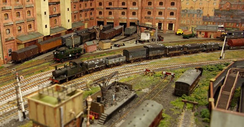
Helicopter shot. If the pilot flew any higher he would have needed oxygen….or more accurately …….I would have fallen off the step ladder.
There are 5 more wagons and the Brake Van out of shot! That is a total 18 wagons (Well wagon counts as 2) which is about the longest I can fit in the storage yard. In addition to the curve there is a slight gradient. TO my surprise the 14 xx managed it with ease.
Rather begs the question of why Dapol and Hornby persisted with traction tyres after they changed the chassis and upgraded the motor. Hard to believe this is just because of the Zimo Chip plus a Supercap.
A surprised and happy camper in Vancouver
John
Posted

Full Member
I thought that the drivers had a groove machined into them to accept the traction tyre. I can recall older locos starting to waddle somewhat when the tyre either fell off or snapped - the wheel/groove not making a good connection with the track. Is this not the case with the 14xx?
Barry
Shed dweller, Softie Southerner and Meglomaniac
Posted
Full Member
Hi BarryJohn - very interesting.
I thought that the drivers had a groove machined into them to accept the traction tyre. I can recall older locos starting to waddle somewhat when the tyre either fell off or snapped - the wheel/groove not making a good connection with the track. Is this not the case with the 14xx?
Barry
That is correct. I have had a number of derelict 14xx so I sacrificed a couple to replace the grooved drivers on the other two. There is a post about it earlier in the week that shows how I did it. I am very content…. I now have two extra locos!
Belated congratulations on your house move. I suspect you are now living not too far away from where I used to live many many years ago
Best wishes
John
Posted
Full Member
I have just realised that my post which you replied to was carelessly worded………my apologies
I should have made it clear that it was the grooved drivers that were replaced with non grooved wheels rather than just the traction tyres being removed
Cheers
John
1 guest and 0 members have just viewed this.