Granby Junction 1948 N. Wales
Posted

Full Member
GWR/LMS OO Gauge DCC RR&Co
[user=6]Petermac[/user] wrote:Hi PeterYour attention to detail is amazing John - I can hardly see the numbers on my locos although this post did make me do a little interesting research.
If one is prepared to dig a little, there's far more to interest the railway modeller than simply laying track ……………..
Am I right in thinking your comment about renumbering Colston Hall is because she wasn't at Chester in 1947 - or am I barking up the wrong tree totally ……………..?
Where are those shots taken on Granby - i.e. what is the rather nice looking stone walling in the background ?
I think I need to settle on a shed for Maxmill having read this ………………………..
I do think engraved plates improve the look of GWR models. For me they are part of the after purchase package I do…..Crew, coal etc. Once you go down the route of buying plates one may as well get ones for a local shed……I dont get totally hung up about it but it is interesting doing the research.
The loco was shedded at Chester in ‘47…….it was a bit tongue in cheek. I believe the actual building Colston Hall was named after the gentleman whose statue was recently dumped in the water at Bristol. The building itself is to be renamed apparently
The shot was taken just outside the north or RH end of the station. The building is a modified Bilteezi kit…….I think it may have been a station kit…..its just fixed flat against the wall…..I will try and get an uncropped shot.
Cheers
John

Posted

Full Member
As well as our favourite 'Great Western Engine Sheds 1947', I also find the Shed Bash website a useful resource, which for example, covers Chester West shed from 1937 to 1959:
Shed Bash UK: Chester West 1937 - 1959
Don't stress though Peter, as the site also shows where other companies locos slept and dreamt of keeping up with the Castles and Kings.
Best,
Bill
At 6'4'', Bill is a tall chap, then again, when horizontal he is rather long and people often used to trip over him! . . . and so a nickname was born :)
Posted

Full Member
I actually thought your Colston Hall have moved to Chester in 1950 ……………………..
I had spent an enjoyable half hour looking at the various Leeds sheds allocations - some interesting names in there and a far greater range of types than I'd imagined. Certainly plenty for me to populate Maxmill with.
I think you'll find there were not many in the power house of England dreaming of Kings and Castles Bill - far too busy admiring our own sleek looking marvels ………………dreaming is for those lacking the real thing … :cheers
However, an interesting link - many thanks. :thumbs
'Petermac
Posted
Full Member
http://www.greatwestern.org.uk/m_in_gwr_sheds.htm
Hope you are keeping well
Best wishes
John
Posted
Full Member
I put it down to age and isolation John - the penny simply hadn't dropped about Colston - in fact, until he ended up in the docks, I'll admit I'd never heard of him…………………………. :oops: :oops: :oops:

I hadnt either…..I had to google it. You can imagine my shock when I remembered my Hall
Posted

Full Member
Peter is absolutely right John, your attention to detail is amazing and it makes me reassess my own plans on a weekly basis! Maybe layout 2 will be a little more fixed in time, location and history!!
Michael
Posted

Full Member
My choice depended less on the sheds issue as Kings coming to the W-H region typically were domiciled elsewhere. Makes life easier, James I and George I are relatively safe I think :lol:
 Last edit: by Colin W
Posted
Full Member
As for George 1st, whilst I never actually met him, I'm told he couldn't even speak the language of his subjects when crowned. I'll bet therefore, his Coronation was a rather dull affair ……………………..but then I also understand the Kings you refer to were also rather dull characters when compared with Gresley's A4 "Streaks" ……………..
:pedal
'Petermac
Posted
Full Member
Last week was a bit of a disaster!
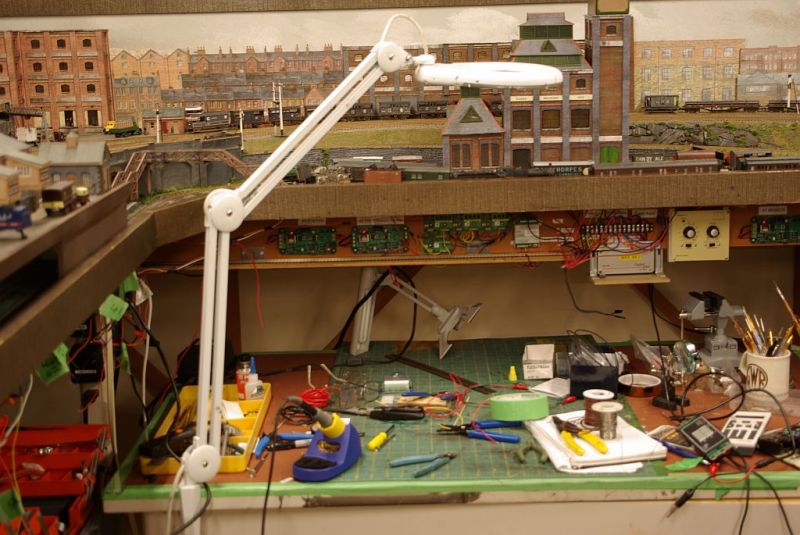
While re-connecting a loose wire on my test track panel I managed to create a short circuit which closed down the layout completely and took 3 full days to sort out.
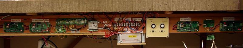
The test track is mounted below the main layout. Its a 10' long piece of straight track divided into three blocks which I use for loco testing and RR&Co profiling. One of the blocks can also be switched to become a Lenz DCC programming track

With the test track not being used on a daily basis I attempted to save money by "sharing" the three detected blocks with three blocks on the main layout.
The panel below enables me to switch between either track and test or test and programme. It contains the occupancy detectors for 8 blocks….3 of which ( 761, 765 and 767) are the "shared blocks"
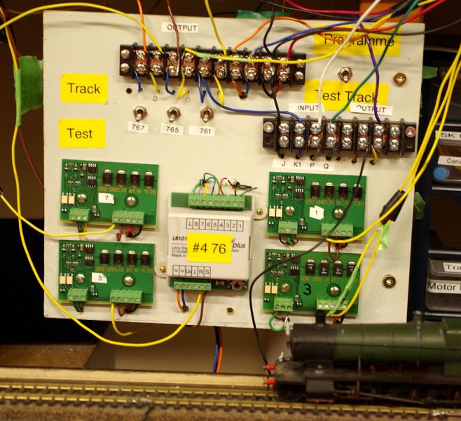
This is a retro shot…….the original panel had a lot less labels and was somewhat Heath Robinson……..hindsight is such a wonderful thing.
I managed to create the short by mistakenly attempting to connect a DCC wire to the 16 v AC turnout circuit……….not recommended.
Normally when I do something stupid like this the remedy is simple. Disconnect the offending wires, turn the power off and on again and all is well. Not on this occasion……the system remained down and there was no obvious means of correcting it. For a moment I thought I had blown the Lenz Control Unit.
Fortunately that was protected by PSX circuit breakers, one of the best investments I have ever made …
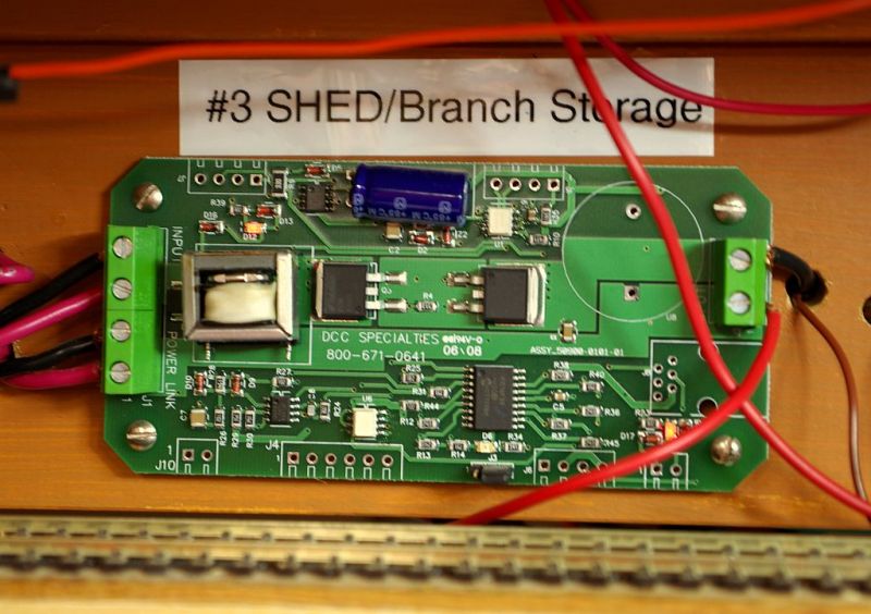
The DCC output from the Lenz control unit is divided into 4 separate sections each protected by a PSX
In theory a short on one leg should not close down the other three however I am afraid over 13 years of modifications and repairs there has been a certain amount of inter marriage between the 4 legs!
I assumed the fault lay with the switch panel and stripped that down tagging and labelling each connection……
Very time consuming and to no avail……no faults
Finally as a last resort I disconnected all the PSX except #3. Having established that the -ve Black circuit was ok I cut the +ve Red circuit down stream of the panel I had been working on. I then proved the fault did not lie there by connecting the cut portion to the +ve output of #3 PSX. I continued this cut and test procedure upstream until, after the third cut, the newly cut section of bus shorted when connected to the PSX output
I then cut and individually tested each dropper connected to the suspect section of bus. After each dropper was tested it had to be soldered and taped.
Eventually I found the faulty dropper……it was connected to an ADSFX (A DCC Concepts point throwing/frog switching device) some distance from the panel. The device is of course connected to both the DCC Bus and the 16v AC bus. I guess my initial error blew some internal safety component. Once I found the source of the problem I remembered that these devices are not as robust as Lenz components and I normally always have the power switched off when working with them.
All that remained was to remove and bin the ADSFX (I temporarily have two non functioning turnouts) rejoin the segments of #3 bus, re- connect the other three PSX and re-assemble the panel!
My wife observed that the whole incident aged me 10 years. A slight exaggeration but it was undoubtedly a singularly depressing 3 days.
However all is well that ends well…….everything is now back up and running…….. the lights on the 4 PSX are winking happily at me and I can continue with my latest project.
Following Colin's example I am hopefully resurrecting a long abandoned Dapol 14xx by replacing the dreaded traction tyre driving wheels from another even longer abandoned 14xx
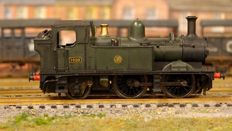
More next week
Regards from Vancouver
Posted

Full Member
Posted
Full Member
Looking forward to seeing your next project, hopefully it will all go smoothly.
Michael
Posted
Full Member
At a stroke, I find myself elevated to the God-like status you hold in my opinion !! I showed your post to Liz demanding that, from now on, she accept that it's not me being useless and that these things happen to the best of us !!!
Joking aside, I have been in that same situation more times than you have ADSFX units !! Electricity, I was always told, is logical and any problems lie in our lack of logic. That, I'm sure isn't true regarding electronics - only a Geek knows what goes on inside those little boxes attached to a paxolin panel ………
If I had a pound for every time I've stripped wiring out looking for an elusive fault, only to find a black wire cuddling a red wire, I'd be able to afford something akin to Miniatur Wunderland !!
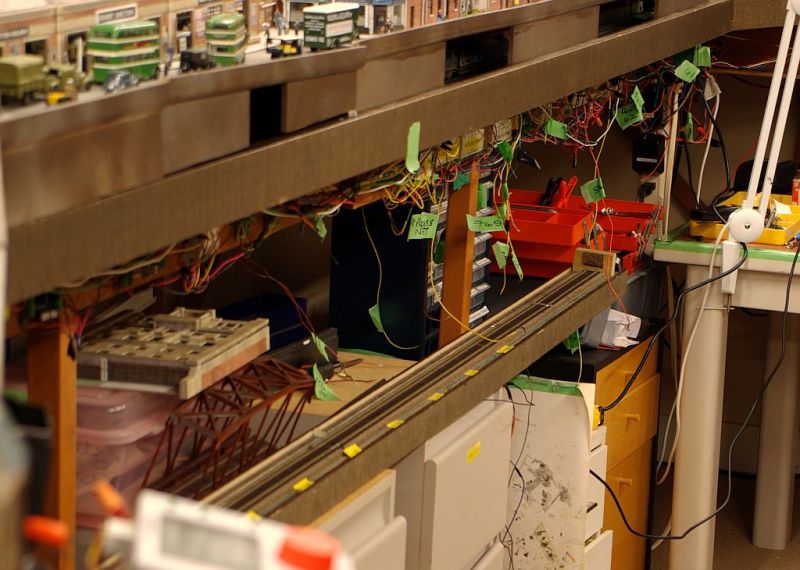
It has been, and is continuing to be, a most interesting series of photographs looking at the complexity of your "below ground" installations - all those electronic gadgets for a DCC system which, as we all know, is just two wires. …………..
I can feel your frustration from here but, more importantly, your sheer joy and relief when you finally found the problem. I suspect there was also an inner feeling of wonder at which stupid B connected that DCC wire to the 16v AC supply …………..
Desperately searching the cloud for that silver lining, at least it gave you the oportunity to tidy and re-label much of your wiring ……………………………
Reading this has reminded me I must get my power districts sorted and utilise my PSX units - which I understand, are currently difficult to find in shops……………..
In spite of the problems John, I've really enjoyed wandering down some of the secret ginnels and back alleys of subterranean Granby ………
'Petermac
Posted
Full Member
Thanks Dave. As I said the PSX are a great investment. I have mounted where I can see them from almost anywhere in the room. They are the first thing I look at when a loco stalls…….if I am running a TC schedule the next is the TC throttle……..if both are on you know it is a track section or the loco.Glad to hear you managed to find the offending culprit - they can be a "challenge". I was looking at buying PSX circuit breakers myself and your experiences confirm my thoughts. I would like to put the points on one and track on the others. Will require some cable reworking I guess - scope for a "challenge" I am sure.
Out of interest why would you want to separately detect the point power supply rather than a defined section of the layout…….the conventional wisdom is to have power districts even if like me there is a single source of power.
Best wishes
John
Posted
Full Member
Thanks Michael………..frustration is absolutely correct…….particularly when it was avoidable and down to my own carelessnessOh dear, John! What a nightmare. I can certainly imagine the frustration of firstly trying to find the problem, and then having to put everything back together again. I am glad that no significant damage occurred (to the controller, for example) but it must be annoying that two points are not working. On the other hand, congratulations on finding and fixing the problem!
Looking forward to seeing your next project, hopefully it will all go smoothly.
Michael
The two points are only temporally out of commission. I have spare decoder capacity so I will be wiring them up later today and the frog polarity will be switched by Gaugemaster 500D which happily, following Peter's suggestion, are already in transit. Meantime passengers for Mold will have alight at Brewery Lane Halt and continue their journey by Bus
Best wishes
John
Posted
Full Member
I always appreciate your replies…….this one was particularly enjoyable :
:hmm Hmm I think its more a case of me falling from a plinth on which you had incorrectly placed me (I guess that is quite topical really :lol:)At a stroke, I find myself elevated to the God-like status you hold in my opinion !! I showed your post to Liz demanding that, from now on, she accept that it's not me being useless and that these things happen to the best of us !!!
The emperor has no clothes is, perhaps, a better analogy.
I am sure that Liz is secretly very sympathetic but wisely doesnt show much for fear you may feel inclined to change the priorities on the to do list (s)
It has been, and is continuing to be, a most interesting series of photographs looking at the complexity of your "below ground" installations - all those electronic gadgets for a DCC system which, as we all know, is just two wires. …………..
I thought of mentioning that! At first sight it does disprove the DCC two wire claim.In fact it is me taking advantage of the power and versatility of DCC that causes all the additional wiring……..most of the wiring on the panel related to occupancy detection and passing that information back to the Lenz controller and subsequently the computor…………if you dont wish to run trains automatically (and many dont) then that is all redundant.
Similarly if you are not running automatically one can question the benefits of using DCC to control turnouts……..its undoubtedly easier to do this via a conventional switch board than remembering turnout numbers and punching them into a DCC throttle.
Strip all that out and you are left with just two wires each connected to the track at intervals. Without any further wiring or switches you can run any number of locos simultaneously, at differing speeds in opposing directions. Of equal importance,you can run one or more locos while leaving other locos stationary anywhere on the track.
Think of the cutting and wiring required to achieve half of that on a DC layout?
You know this already of course Peter but I thought it may be of interest to others. :lol: :pedal
Best wishes
John
Posted
Full Member
Thanks John you could well have saved me a chunk of money.
Posted

Full Member
The other approach is to have point motor circuit(s) and frog polarity changers separate from the track. Unfortunately the current approach is to have them integrated with the track power supply. Which as you rightly point out can cause a lot of problems.
That said, for a decoder to loose it's cv values during a short is strange. Not something I have seen with locomotive decoders. I thought cv values went into eprom. If that is being wiped it points to a design issue in the Cobalts (lack of or inadequate short circuit protection compared to a motor decoder).
Nigel
©Nigel C. Phillips
Posted
Full Member
Hi John. The reason I was thinking of putting the points on their own PSX and track sections on another was because sometimes when I get a short whilst running I end up my cobalt point motors loosing there addresses. Not all of them, but enough to make it quite a pain. On my centre section, with the lower storage areas, I was going to buy a triple unit and run points off of one, lower storage area off of another and the main running area off of a third. Thinking about it, why can't I run the points pre-PSX units and just buy a two section PSX for actual track?
Thanks John you could well have saved me a chunk of money.
Hi Dave
A couple of points
Your idea of splitting the DCC bus into two separate power districts each protected by a PSX sounds perfect. I would do that sooner than later ……..it may well stop the turnout decoders being affected by a short by closing the system down before it affects them
Having said that I agree with Nigel……Accessory decoders should not lose their memory as a result of a short on the DCC bus
We may be able to solve it but I need a bit more detail.
…What accessory decoders are you using (I wasnt sure if Cobalt referred to turnout motor or decoder or both)
…Is it always the same accessory decoder which loses memory when there is a short or is it random?
…. You mention it doesnt happen every time…….is there any similaity between the cause of the short when it does occur.
Best wishes
John
Posted
Full Member
Posted
Full Member
I don't want to hijack either, but have you contacted DCConcepts? It sounds like their auxiliary decoders may not have the same short protection as a regular decoder. In which case a PSX may not do anything as there is still a short (albeit of short duration).
Nigel
©Nigel C. Phillips
1 guest and 0 members have just viewed this.