Granby Junction 1948 N. Wales
Posted

Full Member
GWR/LMS OO Gauge DCC RR&Co
[user=434]John Dew[/user] wrote:That shot took about ten minutes, it will take longer if your new to it but it's just knowing what tools to use.Thanks Phil………I have to work on this layering lark your shots look so much better.
Cheers
John
Phil

Posted

Full Member
A lot longer for me I am afraid……..after an hour struggling with that damn mouse the result doesnt even approach what you achieve……I guess I have just to persevere :roll:.[user=434]John Dew[/user] wrote:That shot took about ten minutes, it will take longer if your new to it but it's just knowing what tools to use.Thanks Phil………I have to work on this layering lark your shots look so much better.
Cheers
John
Cheers
John
 Last edit: by John Dew
Posted
Full Member
The first two, both on insulfrog double slips at the Station entrance, were pretty straightforward. Just replacing Peco Surface mounted points. I am beginning to realise that RR&Co creates a certain amount of wear and tear with solenoid point motors…..a signal is sent every time a route is set, even when the point is already in the correct position.
The third point took a bit longer. It was on the other side of the room at the entrance to the storage yard.
First problem was accessing it:
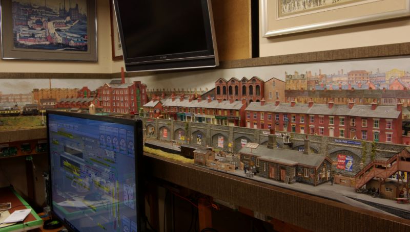
Fortunately the storage yard screen is composed of 30" lift off Metcalfe modules
Disconnect and carefully remove the oversize monitor…….and we are ready to go.
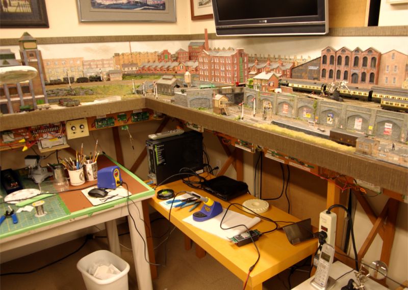
The problem here was similar to the slip motors……one of the solenoids had given up the ghost. Except this was a standard peco motor attached to the point below the baseboard. I was not looking forward to replacing it!
But for once the sun and the stars aligned……
Some years ago I guess I must have replaced the entire point by dropping it in and using conventional rail joiners to slide in (insulating cuts were made further up the lines). In consequence I was able to lift the entire point clear of the baseboard and it was then relatively easy to attach a new motor and frog polarity switch.
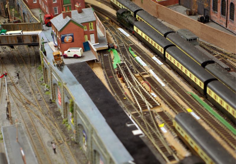
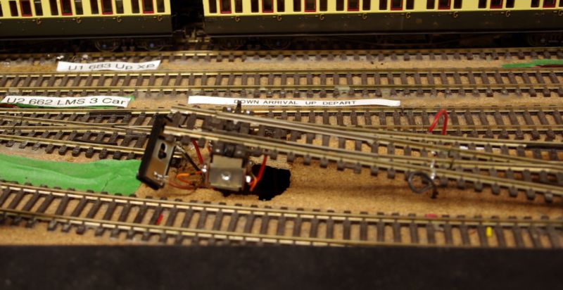
The switch still has to be clipped to the new motor in this shot……….I left it unattached until I was 100% satisfied that the switch was working correctly (years of frustrating experience there)
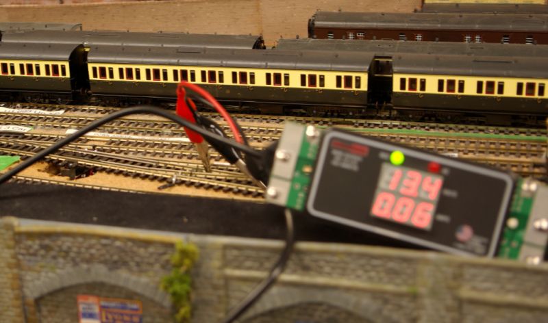
Everything perfect……..
I should have rushed out and bought a lottery ticket!
The gizmo above is a rampmeter…….one of the best tools I have ever bought. I am not an electrician and I must confess I have never really understood how to read a multimeter. This device is idiot proof……if the circuit is good it lights up…..as simple as that.
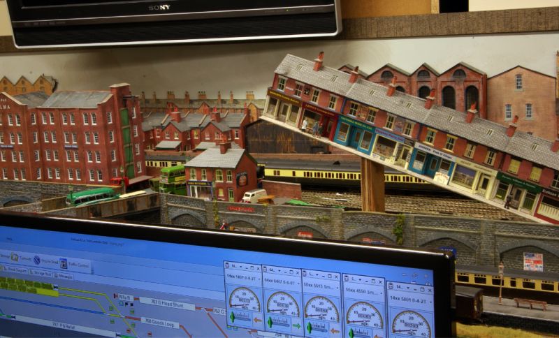
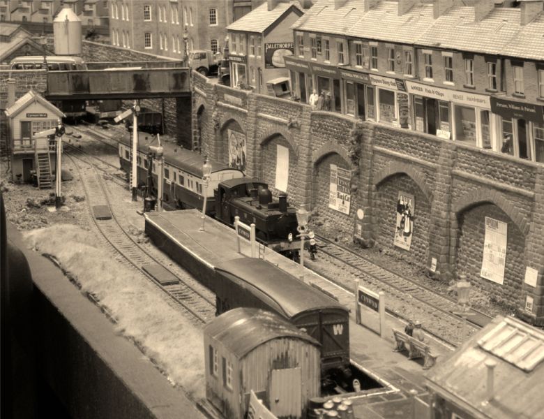
Everything back in place…..The Mold-Bersham autotrain can now be seen entering Cynwyd
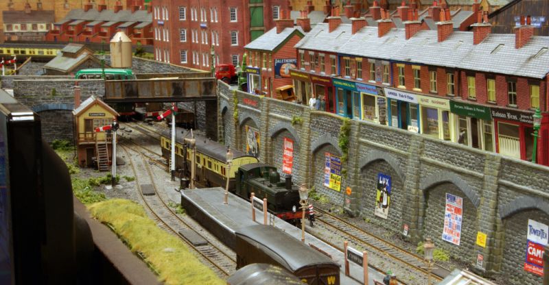
I know its time I showed some locos on this thread……… although in fairness that shot is really a segue into next weeks topic
Meantime………is that a bus on the bridge?
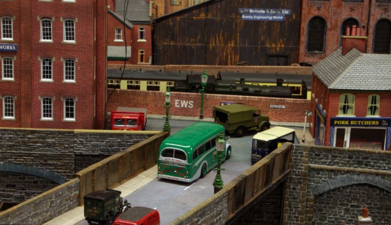
It is indeed……..terrible overworked cliche…..I should be ashamed

Although in this case, I believe, I can be forgiven
Regards from Vancouver where its raining……heavily
Posted

Site staff
I am beginning to realise that RR&Co creates a certain amount of wear and tear with solenoid point motors…..a signal is sent every time a route is set, even when the point is already in the correct position.
I presume that RR & Co doesn't get told the status of turnouts before attempting to operate them?
Ron
NCE DCC ; 00 scale UK outline.
NCE DCC ; 00 scale UK outline.
Posted

Full Member
I love your hidden storage roads - yet another stroke of genius. I think I may use a similar idea on Maxmill (or is it Kingsmill now ?) There are one or two places where I think I'll need to access hidden tracks if things go as planned (I use the word "planned" very loosely…… )
As for the bus - how did you do that panel - I'm guessing they didn't make one specially for you …………………………. :shock:
As ever - gorgeous shots of Granby. :thumbs
'Petermac
Posted

Full Member
Absolutely forgiven John and frankly, a cut above the rest!Meantime………is that a bus on the bridge?
It is indeed……..terrible overworked cliche…..I should be ashamed
Although in this case, I believe, I can be forgiven
Regards from Vancouver where its raining……heavily
Regards from the Loire, where it's a tad overcast today.
Bill
At 6'4'', Bill is a tall chap, then again, when horizontal he is rather long and people often used to trip over him! . . . and so a nickname was born :)
Posted
Full Member
RR&Co think it knows but isnt certain! :lol: In fairness its just the same if you try and turn a solenoid point that is already set with the Lenz controller …..it will still send the signal. That another plus for stall motors like Tortoise.your comment
I am beginning to realise that RR&Co creates a certain amount of wear and tear with solenoid point motors…..a signal is sent every time a route is set, even when the point is already in the correct position.
I presume that RR & Co doesn't get told the status of turnouts before attempting to operate them?
Petermac wrote:
What a stroke of luck there John - something must have told you the motor would fail when you originally installed the point.
I love your hidden storage roads - yet another stroke of genius. I think I may use a similar idea on Maxmill (or is it Kingsmill now ?) There are one or two places where I think I'll need to access hidden tracks if things go as planned (I use the word "planned" very loosely…… )
As for the bus - how did you do that panel - I'm guessing they didn't make one specially for you …………………………. :shock:
As ever - gorgeous shots of Granby. :thumbs
Thanks Peter…….I move those houses quite a bit…..no matter how confident you are it is nice to check the loco uncoupled properly!
I stumbled on the bus at Hattons……it was a Three Pound special……couldnt resist!
I forgot to add this postscript to last nights update:
As the World Cup (of Rugby for the uninitiated) approaches I will refrain from making any predictions but confess to a certain amount of optimism that England will ,at the very least, do rather better than four years ago! The kick off times are horrible for us…..3am. I am recording everything I can, so modelling will take a back seat and I will studiously avoid turning on the Ipad to avoid the inevitable spoilers
Regards from Vancouver……where it is still raining heavily….I guess summer is over :sad:
Posted
Full Member
12 years ago, when I first started to learn about the mysteries of DCC, the lower level branch line was the first section of track that I laid. I am afraid I didnt do a particularly good job. Its a bit uneven in places and in those days if you wanted to isolate the electrofrog points, rather than snip a little wire you, had to make the cuts yourself with a Dremel. I have some horrible gaps….carefully filled but of, course, without power.
The 57xx panniers that take the B Set to and from Granby manage to cope very well with this uncertainty. The autotrain does not! I have struggled for over three years with both a DJM 14xx or the 64xx .
The 64xx is the better of the two but despite constant wheel cleaning and finely adjusted pick ups it still requires far too many little nudges from the sky.
When I get really frustrated I have even been known to substitute this ancient Lima rail car, which I believe I bought in Beatties, Sheffield, in 1998!
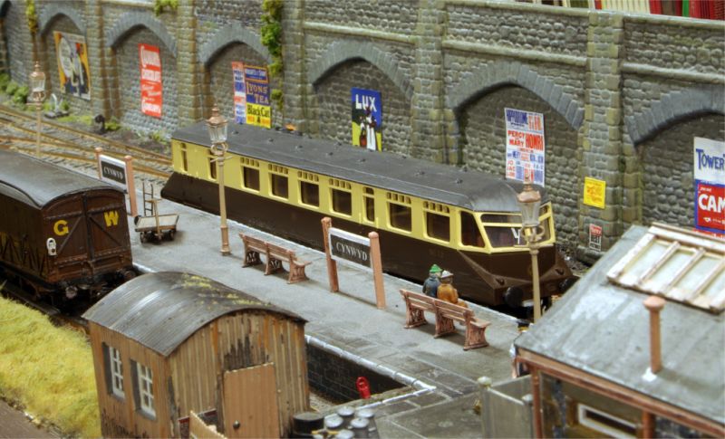
You may well ask why this 20 + year old model, notorious for its pizza cutter wheels, can out perform a modern Bachmann loco?
Well the wheels have been updated and additional pickups have been fitted. However the principal difference is that a Stay Alive capacitor is wired to the decoder.
A capacitor is a sort of battery that stores up power and supplies it to the decoder when the decoder detects a power outage.
I have three in use on Granby. They have some downsides……they are bulky, expensive and used to come pre wired to a specific decoder. I have found the best value for money to be the TCS Keep Alive range. The problem is that I cant abide the TCS decoder with its erratic speed curve.
I was about to hold my nose and fit one in the Autotrain and hard wire it to the 64xx when I discovered that you can now buy the TCS capacitors separately and they have been on a diet…..much slimmer:
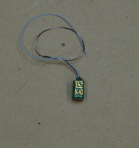
The next problem was how to attach the KAT2 to the decoder…….the 64xx is designed to accept a 6 pin decoder that plugs directly into a pre-wired socket…..ie no wires.
I have been meaning to try a Zimo decoder for some time. They have a relatively inexpensive 6 pin decoder with two largish solder pads for the blue (+ve) and black/white (-ve) wires.
I emailed John Gymer of Youchoos to ask his advice before ordering from him. He was super helpful and made a number of very helpful suggestions…….including an even smaller and far less expensive way of storing power …..unfortunately the KAT2 was already ordered……..but more on this later.
Here is the rig to be fitted inside the 64xx
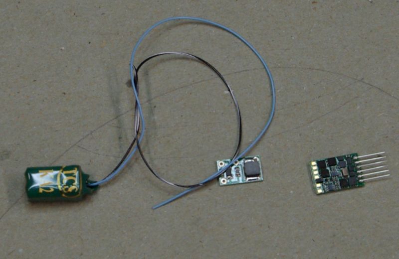
KAT2 Capacitor to be connected via a tiny protective device (Lifelink) to the Zimo decoder….the two "largish" solder pads are bottom left.
I had intended to put the capacitor either on the cab floor or in the bunker but had forgotten that the decoder socket is right at the front of the loco.
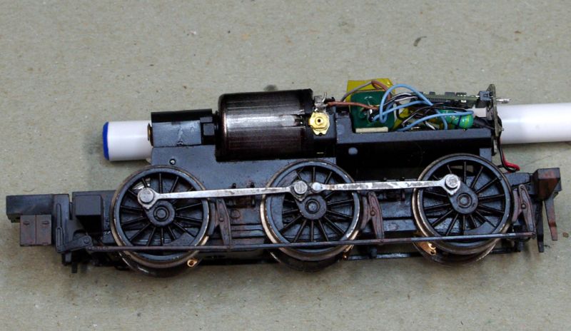
Fortunately I was able to fit both the Lifelink and KAT2 underneath the decoder
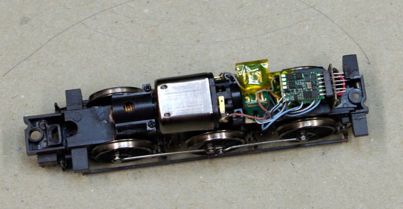
I have learned to take things like this very slowly and carefully but even so I dont think this took more than an hour to complete.
And here is the result
[yt]0GSO-d0bzW8[/yt]
I dont expect to ever have to run the loco over 18" of un-powered track but clearly there is now sufficient power in reserve to overcome any gaps,dirt or insulfrogs.
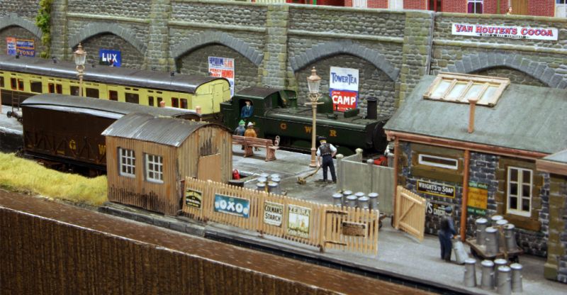
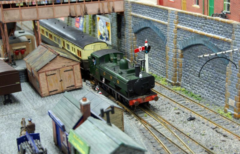
Here we see 6407 complete with new fireman and a new headlamp moving smoothly over a turnout previously known as Stall point!
I now have a cunning plan to deal with the DJM 14xxs
Regards from Vancouver
John
Posted

Full Member
most impressive, there must be a fair amount of capacitance there to give such a long run on without power. Do you know the specs for the TA2 device?
I've typically used 2200uF capacitors on my locos and find these deliver at best less than a second of running but more than enough for my insulfrogs. That passes the crude reality test that at 15V the capacitor holds 33mCoulomb of charge which equates to 33mA for 1 second (discharge is neither linear nor complete so this is exceedingly rough).
BTW for anyone thinking "maybe I could use the super (Farad sized) capacitors" these have very low current capability and so are unsuited to deliver mA flows typically needed in model locos. Found this out when a friend built a circuit with them for me to try out.
Colin
Posted
Full Member
:???: :???: :???: :???: I'm lost ………………………………………………………………………………………………..
I've typically used 2200uF capacitors on my locos and find these deliver at best less than a second of running but more than enough for my insulfrogs. That passes the crude reality test that at 15V the capacitor holds 33mCoulomb of charge which equates to 33mA for 1 second (discharge is neither linear nor complete so this is exceedingly rough).
……………………………………………………………..
'Petermac
Posted
Full Member
If you feel that 18" is too far to run without control, then the Zimo decoders have a CV to adjust how long the loco will run.
Cheers Pete.
Posted
Full Member
Thanks ColinHi John,
most impressive, there must be a fair amount of capacitance there to give such a long run on without power. Do you know the specs for the TA2 device?
I've typically used 2200uF capacitors on my locos and find these deliver at best less than a second of running but more than enough for my insulfrogs. That passes the crude reality test that at 15V the capacitor holds 33mCoulomb of charge which equates to 33mA for 1 second (discharge is neither linear nor complete so this is exceedingly rough).
BTW for anyone thinking "maybe I could use the super (Farad sized) capacitors" these have very low current capability and so are unsuited to deliver mA flows typically needed in model locos. Found this out when a friend built a circuit with them for me to try out.
Colin
I had no idea you were so knowledgeable. I am really glad that I didnt pretend that I was an expert on all this! :lol:
Now I know where to go when I run into trouble with the next project! I bet you know all about tantulums? Until a couple of weeks ago I thought they were spiders………dont give the game away until I find out whether they will work in a 14xx.
Here is a link to the KAT2 page on the TCS site …..http://tcsdcc.com/1456
Best wishes
John
Posted
Full Member
Hi John,Thanks Colin
…..
Now I know where to go when I run into trouble with the next project! I bet you know all about tantulums? Until a couple of weeks ago I thought they were spiders………dont give the game away until I find out whether they will work in a 14xx.
I'm afraid I already let the cat out of the bag re tantalums; see my Post #12 over on Westown where I show a photo of my install in a Class 57xx with a number of them dotted around!
I haven't posted yet on my install in my 48xx Hornby (R 2778; from 2008) and if you have that version, the loco has a fairly inefficient motor compared to the Bachmanns. I needed 4400uF to get about 3/4 of a wheel turn of run on. Still that is enough for the insulfrogs and it is now an excellent runner!
Colin
Last edit: by Colin W
Posted
Full Member
Cheers
John
Posted
Full Member
Hi John,
If you feel that 18" is too far to run without control, then the Zimo decoders have a CV to adjust how long the loco will run.
Hi Pete
I knew Zimo had that capability but I dont know which Cv it is. Although in fairness I dont think it will be an issue on my layout.
There is an amazing number of Cvs on the Zimo. Until now I have standardised on Lenz and I only change Cvs 2-6 because Train Controller produces the speed curve when you profile.
I did the same thing with the Zimo except for 6 which I left at the default (30%). I must say it produced a very smooth curve. So far I am very impressed.
Are there any other Cv changes I should have made?
Cheers
John
Posted
Full Member
[user=2170]Colin W[/user] wrote::???: :???: :???: :???: I'm lost ………………………………………………………………………………………………..
I've typically used 2200uF capacitors on my locos and find these deliver at best less than a second of running but more than enough for my insulfrogs. That passes the crude reality test that at 15V the capacitor holds 33mCoulomb of charge which equates to 33mA for 1 second (discharge is neither linear nor complete so this is exceedingly rough).
……………………………………………………………..
 ……you are not alone!
Posted
Full Member
Cheers Pete.
Posted
Full Member
If the loco continues for some distance after the power is cut, how will this effect RR&Co or can you either specify exactly how far it will run or alternatively, does it always run the same distance, in which case, you could cut the power early ?
If not then, as with many things in life, solving one problem would appear to precipitate another ………………
'Petermac
Posted
Full Member
Cheers Pete.
Posted
Full Member
I wonder if this is the case with all stay alive's or just Zimo …………………..
'Petermac
1 guest and 0 members have just viewed this.