Granby Junction 1948 N. Wales
Posted
Legacy Member
GWR/LMS OO Gauge DCC RR&Co
Hi JohnSorry if I have held you up by not replying quicker but have been having internet connection problems for the last 48 hours ( I think there is a game of footy on somewhere which may account for it :roll:)
Right to your questions .
Gates - Yes as a general rule the top gate of a narrow lock is single and the bottom ones are a pair . Peter is quite right about broad canals having paired gates top and bottom which is due to the width of the lock would mean a single gate would be too heavy to use .There are exceptions on the narrow canals where there is a single gate at both ends and this is usually due to local engineering or access problems.
Height of towpath - usually less than 2 feet , may only be a couple of inches but again its a local conditions thing and depends a lot on the topography in the immediate area .
Materials - Whilst earth and grass banks would be normal for country stretches brick, stone, concrete or even timber would be used in built up areas or anywhere where the boats would likely have regular contact with the edge such as approaches to locks , tight bends , narrow stretches etc . As the canals were local affairs when built and there was no real long distance transport system in existance the materials would come from the immediate area , so whatever your predominant construction material is for the town then its likely to be the same for the canal.
Basin Layout - Gets an AAAAA++++++:patheadShould look great . I do like those Langley warehouses . They remind me of the warehouses in Gloucester Docks . Another good building for those that dont want to go the kit route is the recently intrduced Oakhill Brewery building (Bachmann ?)
Hope that covers everything but shout if there is anything else I can help with.
Richard. A sorely missed member who lost a brave battle in 2012.

Posted

Full Member
I am not sure if I want to talk about footy after yesterdays game…..I taped it…..kept the tv and radio off and avoided this forum in case anyone leaked the result……what a waste of time……..I dont think HMV in Scotland need to worry about their "Anyone but England" posters…………..sorry rant over and probably in wrong thread

Posted
Legacy Member
Richard. A sorely missed member who lost a brave battle in 2012.
Posted
Full Member
Thanks Richard…….I wish I could
I can push it back a bit but I assumed it should be pretty close to the waters edge
In any event I dont think I can leave it without increasing the side depth……its more or less in the centre of a 10' run where the 18' left hand side connects with the 18' right hand side via the duck under
The green tape at the right marks not just the end of the duck under but the start of a 4' deep baseboard
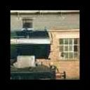
This original shot probably shows the depth more clearly
PS Thanks for the tip about the tow path coverings…….that was on my list of questions!
Kind Regards
Posted
Legacy Member
Whatever suits you best.
Richard. A sorely missed member who lost a brave battle in 2012.
Posted
Full Member
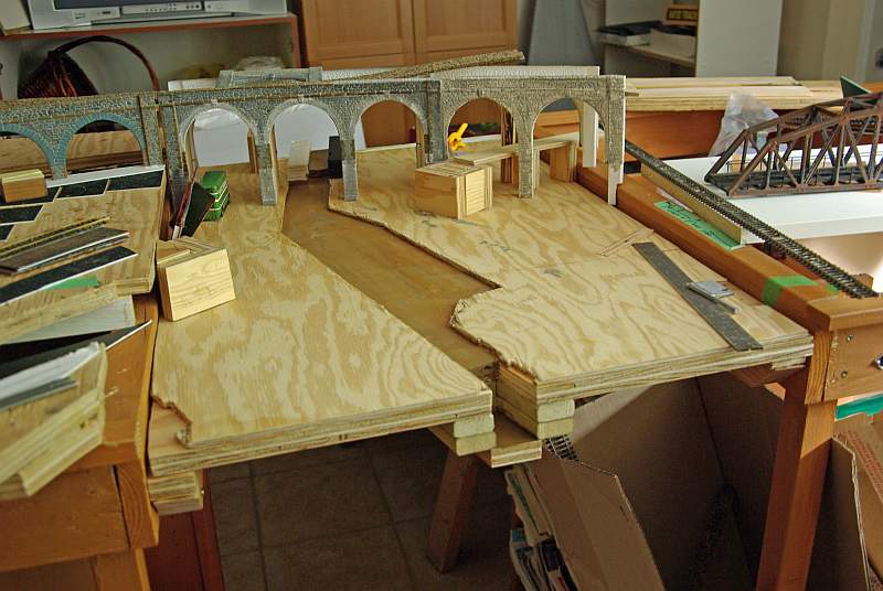
However I am learning a great deal from Richard………..so with his green light I went ahead and cut out the canal outline

In the foreground you can see I have cut out the bottom lock below the base board and set up the supports for the First Bridge to allow for towpaths…………….if you are wondering about the first notch/recess……..its a mistake………the second recess behind the gate is in the correct place. Its where the gate is located in the open position………..the wrong notch will be hidden by the tow path and revetments.
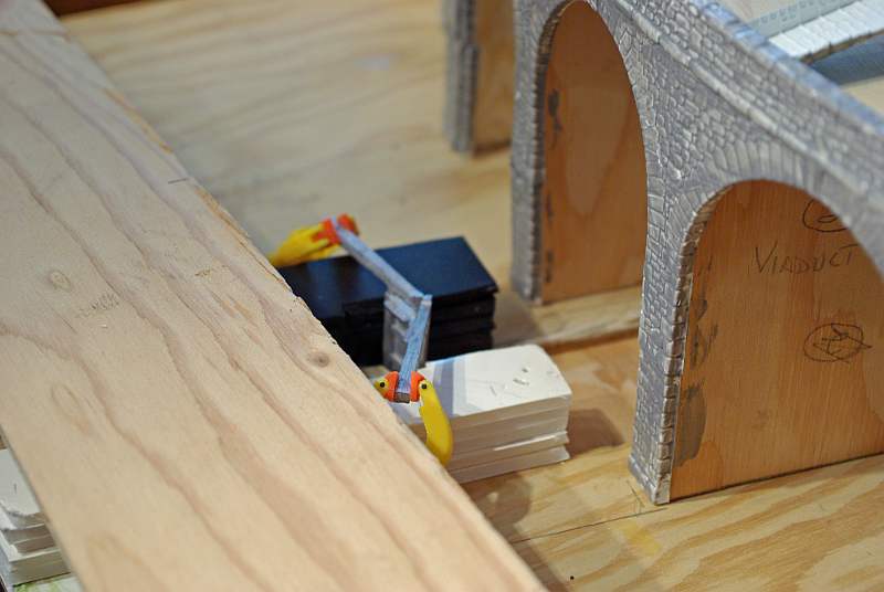
Here is a close up
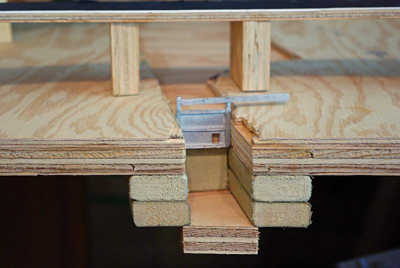
Some fine carpentry here! The lock walls will be covered with Slaters plasticard and I will build a stopper ledge in front of the gate to prevent the gate being opened the wrong way by the upstream pressure
And from the other side you get a good view of the tow path and correct recess…………all the evidence of rubbish cutting will be concealed by plasticard!

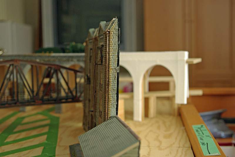
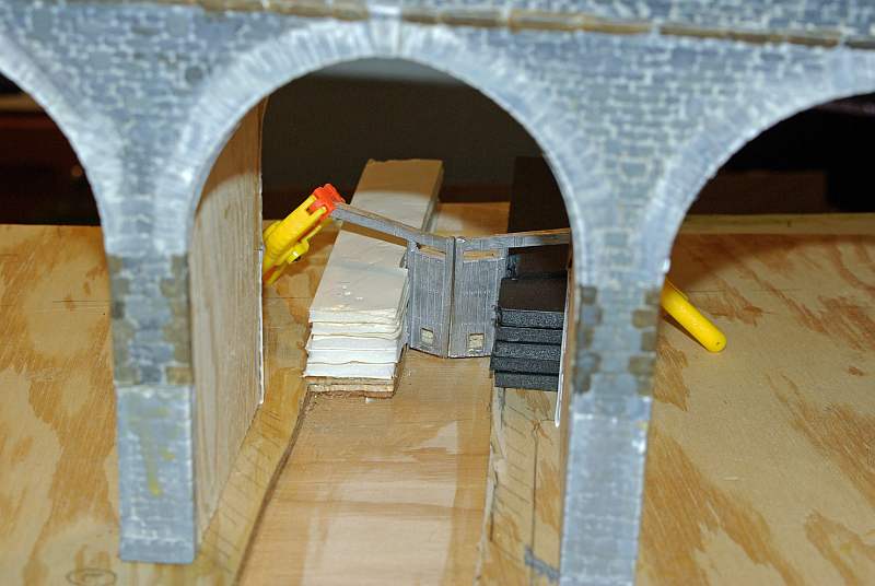
This shot of the upper lock gives an indication of the change in levels. Since taking the photo I have realised the gates are the wrong way round……..in this position the upstream pressure would force the gates open!!!

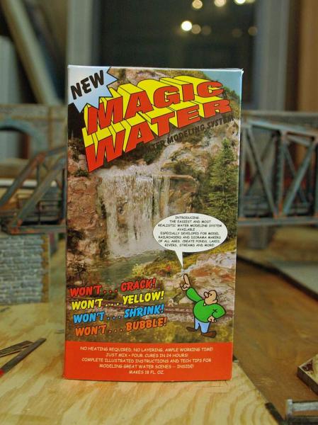
These pieces of foam board are not the extent of the upper level but are are installed so I can clad out the interior before pouring the Magic Water
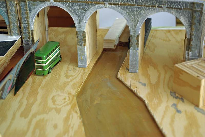
But they have exposed a couple of problems…………at the very edge of the baseboard is Bridge 4 connecting the coal mine which I have now decided to double so I can store both Coal Trains:
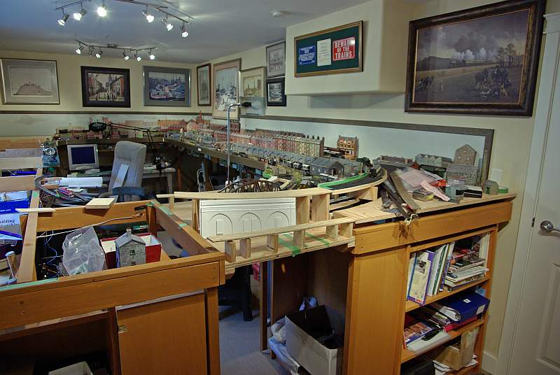
So I have some head room problems…………(hence the double decker bus lying around)…………I think the canal is ok….. its about 8'…….. but I cant get the roads to that level so I will just have to suggest the start of a slope running between higher ground on either side

This is the main problem (ignore the uneven tow path……the left bank became unaligned……but it is still 3' Richard….. honest !anyway I can shim it out a bit)
My problem……how do I get the tow horses from one level to another?
I guess there were not too many in use in 1947 but at the very least there should be some vestige of the ramp (s) and I suspect they would have remained in place any way………….certainly in my only experience of canals (Canal du Nivernais a far cry from North Wales) there were ramps
My question…………..can I get away with just one ramp ideally on the left bank and what is an acceptable gradient in visual terms (even if unrealistic prototypically)………….the increase in height is 1" could I get away with 1:10???
Finallly I have made a start at painting the canal base. Having learned from Wayne I have a test bed as well but I need to get the edges painted because I want to install the revetments and lock gates before pouring the water

This is just the first coat and I have found it difficult to reproduce…………it looks brighter here than in situ but my first reaction is that it is a bit too reddy brown………………closer too the Ganges in flood than the Leeds and Liverpool canal
Comments very much appreciated
 Last edit: by John Dew
Posted
Guest user
I looked at some online images of the canal - some really lovely scenery along there.
Mike
Posted
Legacy Member
Thats coming along very nicely . Dont worry about headroom for the canal bridge - there are many bridges and tunnels where the headroom is only a couple of inches above the boat and even some where you have to add weight to the boat to lower its waterline ( one of our local ones its a regular occurrance to hijack half a dozen towpath walkers to sit on the boat to get it through the bridge :roll: ) and others where if there is a lock handy water has to be run out the pound to lower the boats airdraft.
As to horses on the canal - they were around in considerable numbers in 1947 and actually some in commercial use up to the early 1960's . Rare to see them these days but the Horse Boating Society endeavours to keep their working practices alive as well as the special type of narrowboats that were used by them.
There are some very steep ramps around especially where a towpath comes under a bridge with a lock abutting the bridge and in these cases raised brick strips are put across the towpath edge to edge every couple of feet to give the horse grip. Where a bridge is too low for a horse to get under sometimes a trench would be cut in the towpath but more usually there would be a ramp up each side of the bridge and the horse would be detached and walked over the top . Where this happened a lot and the canal towpath needed to change sides certain canal companies installed what was known as a Turnover bridge which allowed the horse to cross and go under the bridge without detaching . The construction of that type of bridge in model form would be a challenge.
Hope this helps.
Edited to mention the average drop level of a narrow lock is 8 feet - as usual lots of exceptions from 6" drop to 14 feet where two locks have been rebuilt as one.
Also the ramp up doesnt have to end at the end of the lock but can end anywhere along the length of the lock to ease the gradient.
Last edit: by Wheeltapper
Richard. A sorely missed member who lost a brave battle in 2012.
Posted

Full Member
I shouldn't worry too much about the colour of your canal.Our area in the Northwest of England is surrounded by canals,which seem to vary from muddy brown to pea green.
Your colour looks perfectly natural to my eye!
Cheers,John.B.
PS. If you need/want photo reference for a turnaround bridge,there is one not a million miles away from me!
Last edit: by spurno
Posted
Legacy Member
Would that be Marple John ?PS. If you need/want photo reference for a turnaround bridge,there is one not a million miles away from me!
Last edit: by spurno
Richard. A sorely missed member who lost a brave battle in 2012.
Posted
Full Member
Mike….. the stonework isnt finished at all (its a mix of previous painting and the first coat on the new bits) but even the first coat reveals the detail. I have been struggling with when to start properly painting the viaduct because I need to clad the interior first and I didnt want to do that until I had sorted the ramps
John…..thanks for the offer but with 4 bridges already and Richard's comment about a challenge to build I think it will have to be "off stage" maybe in the lower lock area
Richard…..I knew I had written that bit about headroom badly…..its not the canal I am worried about because I well remember ducking under the bridges in France…..rather it is the road bridges on either side of the lock which because the approach cant climb very much means that the lock will look a bit like a projecting penninsula……………..but now you have helped with the ramps I think I can see a work around
Thank you so much for the tips about the ramps that you have given me. It is all much clearer now. I really like the idea of raised edges to help with the grip………..similar to the battens on GWR Halt ramps
Edited to mention the average drop level of a narrow lock is 8 feet - as usual lots of exceptions from 6" drop to 14 feet where two locks have been rebuilt as one.
Also the ramp up doesnt have to end at the end of the lock but can end anywhere along the length of the lock to ease the gradient.
You dont miss anything do you? Both locks are about 12'. I can and will raise the bottom of the lower lock so that the drop is reduced a bit…..its very simple. As far as the top lock is concerned the drop was driven by the lock gates……but on reflection they should be cut down because the bottom shouldnt show downstream…..which means I can reduce both the lock height and drop a little as well
I will let you know how I get on
Kind Regards
Posted
Legacy Member
You dont miss anything do you? Both locks are about 12'. I can and will raise the bottom of the lower lock so that the drop is reduced a bit…..its very simple. As far as the top lock is concerned the drop was driven by the lock gates……but on reflection they should be cut down because the bottom shouldnt show downstream…..which means I can reduce both the lock height and drop a little as well
John
The average depth of water in a canal is between three and four feet so you are not going to see the bottom three or four feet of the downstream lock gate as that touches the bottom of the canal and if you can see it then any boat in the lock will not be able to get out as there wont be enough water to float it . Not that I am saying this has ever happened to me of course :roll:
Actually looking at the picture of the lock gate I dont think the manufacturer has got the paddle holes in the gates in the right place if they are portraying a full gate as when you empty the lock the hole usually ends up at water level with 3ft or more of gate still under water .
Last edit: by Wheeltapper
Richard. A sorely missed member who lost a brave battle in 2012.
Posted
Full Member
I was going to ask you about the paddle holes
The bottom gate is set up so that the lock gate beam is more or less the correct height (4'?)
I see what you mean about the paddle holesI think I have set up the bottom gate correctly so on this shot the paddle holes should be higher or there should be more gate.
In view of your comments I will raise the water level in the lock with some plasticard
As far as the upper lock gates are concerned:
The paddle holes should just be appearing above the water line? So rather than attept to cut into the canal base I propose cutting the gates down and strip off 1 or 2 layers of foam board
Would that work?
The photos you sent were superb they really helped me get a sense of what I have to do with the upper lock not least of which is make sure the stonework isnt too neat and tidy…..perfect for my style of modelling. I see I have to add steps to the ramp…no problem and I liked the way the lock curved and the ridges for the guy pushing the beam?
Incidentally on the photo there is a handle inserted in the beam which the Langley kit doesnt have…..its easy enough to model but does this mean the beam itself should be lower
Because I believe I need to install/embed the gates before I pour the water I am going to have to assemble and paint the kits first.
Langley talk about the gate timbers being brown and the beam and metalwork black with some white. In France I recall the metalwork was often a sort of grungy green……would that be wrong in North Wales? I am going to do my usual routine and paint the sub assemblies pristine assemble them and then weather them as a whole
Richard with all the other stuff you have going on I cannot thank you enough for the the time and trouble you are taking on this project……you have no idea how helpful your replies are to me
Kind Regards
Posted
Legacy Member
Height of lock beam - easiest way of describing it is to say if you stand with your back to the beam at the furthest point from the gate you should be able to push the gate open with your backside by leaning against the beam which is the safest way to operate them.
Handles on gate beams - I think they came in later as did lock access ladders - Early Elfin Safety.
Paddle hole positions - dont think the top gate one is far out and the easiest answer is to reduce the gate height on the bottom gates . But hold off for now and I will try to let you have a picture that will explain it better . Might take a little while as I am getting rather tired and may have to go off for a kip before continuing.
Richard. A sorely missed member who lost a brave battle in 2012.
Posted
Full Member
Absolutely no rush……..just take your time……and take it easy :thumbs
Posted
Full Member
No Richard,we've got one much closer than that,near St Georges Church in Hyde.on the Ashton to Romiley stretch….although Marple locks aren't a million miles away.(I've often fished there in the past)[user=201]georgejacksongenius[/user] wrote:
Would that be Marple John ?PS. If you need/want photo reference for a turnaround bridge,there is one not a million miles away from me!
Do you know our area then???
Cheers,John.B.:thumbs
Last edit: by spurno
Posted
Legacy Member
There used to be a good model shop just along the road from the hall .
I think I know the bridge you mean and if memory serves me right its not that far from where The Horse Boating Society have their HQ at Ashton Junction .
Did quite a bit of fishing at Goyt Valley Park Lakes when i was last there about 15 years ago.
Richard. A sorely missed member who lost a brave battle in 2012.
Posted
Full Member
Cheers,John.B.
Last edit: by spurno
Posted
Full Member
Progress has also been sporadic but as we are about to go away on the boat again I thought I had better do an update although nothing really startling has happened
I have clad in the pillars and under the arches of the viaduct
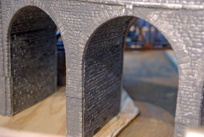
As always the camera is cruel and the joins stand out quite sharply but this is just the mortar undercoat and I think I will be able to conceal them a bit…..fortunately there are other bridges in front.
The painting of the viaduct is quite laborious but you can see some of the progress particularly on the righthand arch. Normally I take this boring stuff away in the summer and do a bit at a time on the boat but I cant find a box big enough to carry the structure…..so its going to take a while
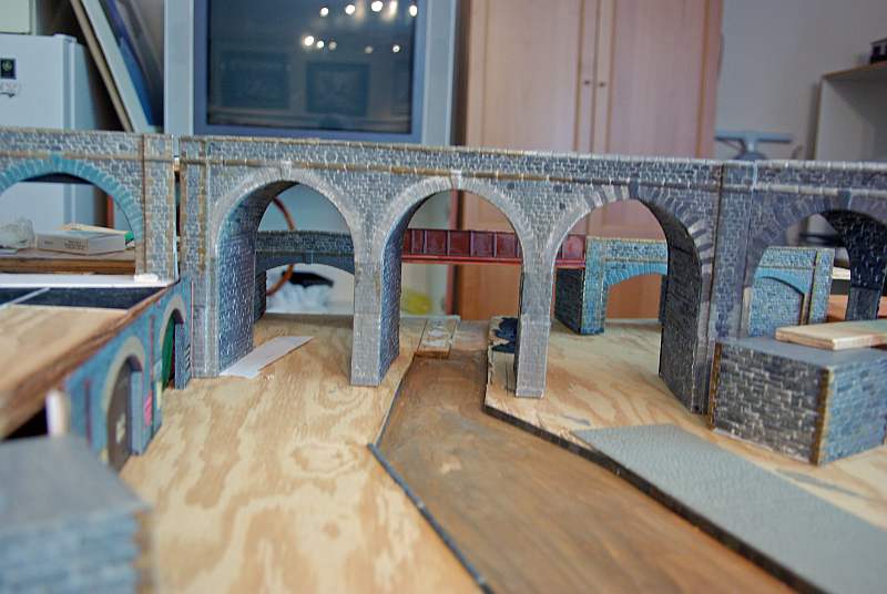
I have clad the supports for the girder bridge and also the bridge for the coal mine at the rear. I have removed the viaduct for a clearer view

The arches mirror the three arches on the viaduct. The left hand one is the main road, the righthand a subsidiary road from the warehouse and the centre the canal with the upstream lock under. I have ripped out the foamcore I built for the lock. I wasnt happy with it and Richard has sent me some photos which are really useful so I am starting again here. The Wills varigirder bridge has to be weathered and secured and doesnt bear close scrutiny from a civil engineer!
I have been a bit worried about masking the 4" drop between the main baseboard and the canal section but I think I have,at least, solved the bit between the viaduct and the girder bridge
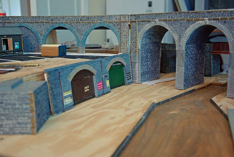
This is a Wills Arches kit from a previous layout and with a bit of fiddling should make a little garage scene just off the main Road
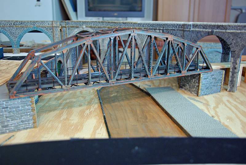
Here is the Girder bridge on its supports.
On the right hand side I have started laying Wills granite setts which will be the quayside for what I am now calling Richard's Wharf……..at least I can acknowledge his contribuition to this project that way
I have started putting in the revetments or canal edges using Slaters sheets
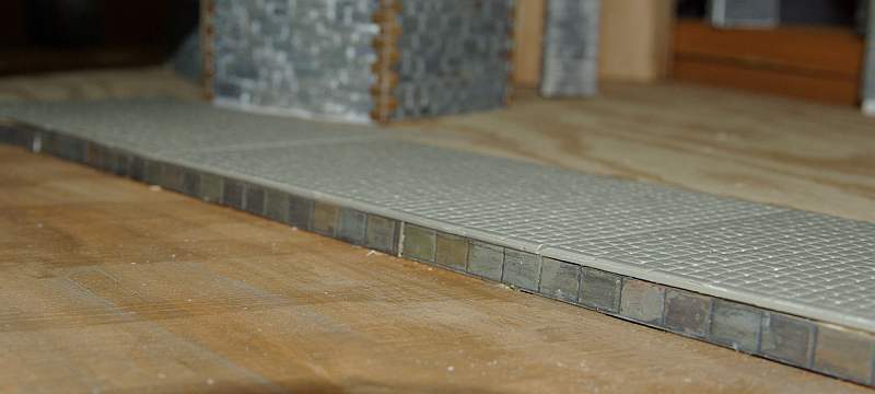
These are a little big …….there should be 2 courses I think, but I have to add 1/8" of water so only 1/8" will show. The Wills sheets are a lttle too thick as well but I didnt like the look of the Slaters cobblestones
On the other side I am just using the narrow strips from the Wills Sheets because the plan is to have a cinder tow path
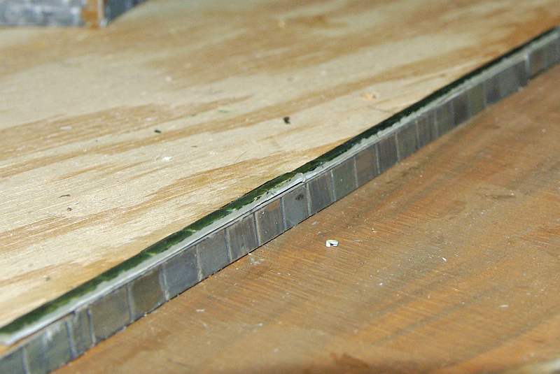
These strips are from the old layout and will be repainted and grass and weeds added. Apart from cleaning the canal bed I need to apply a few more coats of paint before pouring the water
This is the downstream lock which has been raised as Richard suggested.

I added a plasticard base which will retain the water better. There is a ledge to retain the lock gate which has been cut down so that the paddle gate is correctly positioned. I didnt allow for the sidewall thickness so I am filing the gate down a bit to eliminate the bow.
With a slight change of architecture, in theory it will finish up like this!

With the aid of this
I am away for about a month now so apart from painting walls not too much will get done but I should be able to access the internet occasionally
Regards from a hot and sunny Vancouver
Posted

Full Member
Happy holidays.
1 guest and 0 members have just viewed this.