Granby Junction 1948 N. Wales
Posted

Full Member
GWR/LMS OO Gauge DCC RR&Co
I'd love a sailing trip like that………………………:sad:D
'You may share the labours of the great, but you will not share the spoil…' Aesop's Fables
"Beer is proof that God loves us and wants us to be happy" - Benjamin Franklin
In the land of the slap-dash and implausible, mediocrity is king
"Beer is proof that God loves us and wants us to be happy" - Benjamin Franklin
In the land of the slap-dash and implausible, mediocrity is king

Posted

Full Member
[user=11]Novice[/user] wrote:
The whole scene works very well and the detail gives that cluttered industrial look. Very nice. I like the way you have used card to provide the hard standing in the area of the brewry complex, that works well too. How did you eventually decide to conceal that point motor? It would be good to see the final version.
Bob(K)
The point motor is concealed by the water tower……you can just see it through the windows on one of the shots………almost looks like machinery!
I dont know about splicing but I will pack a modelling tool box and try and fix kaydees and weather the goods stock for the brewery
Regards
Posted
Full Member
The point motor is concealed by the water tower……you can just see it through the windows on one of the shots………almost looks like machinery!
Oh yes, very effective. I did wonder how you would do it and it does look the part too.
Bob(K)
Posted

Full Member
It really does look goood and the different photos make it almost like being there - almost, but not quite !!
I think you've created an excellent "industrial scene" (and even with the odd bit of your humour creeping into the text :cheers). It all looks both functional and busy, "planned" yet suitably "chaotic". Just what was required and with enough in there to keep at least me, busy examining each shot for quite some time. :pathead:pathead
'Petermac
Posted
Full Member
Its now almost 8 weeks since I last posted. I havent been totaly idle since finishing the brewery. Sailing and Gardening apart I kaydeed and weathered a couple of rakes of wagons for the brewery and with somewhat limited success chipped a Dean Goods and two split chassis 57xx. I also spent rather too much time playing with RR&Co
But if the truth be told I have been procrastinating. Finding any excuse to put off addressing ……the gap
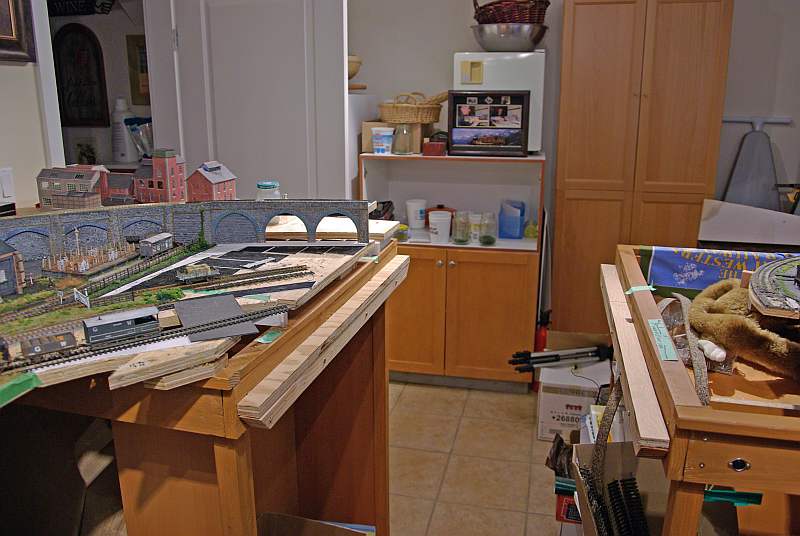
and looking towards the work bench and brewery
Clearly a critical section………….until bridged I cant develop the long left hand terminus (unbuilt) section with the completed storage yards and branch on the right hand side.
I contemplated a lift off section but took fright at all the potential connection problems……so I came up with a classic Canadian compromise………I have installed metal dowels and sockets but for as long as I am agile enough its a duck under…….at least it keeps me fit!

The left hand green tapes represent a road and the long section on the right a canal with a basin and at the end a lock
I have bought a Langley Lock kit and I am still trying to get my head around the dimensions……I had no idea narrow boats were so long……sure eats up the space
Apart from the challenge of a canal (which I have never built before) I have to create a number of bridges at 36" radius connecting the fixed tracks on the left hand side so I have set up some mock ups………………for once this thread is current the following shots were all taken this morning
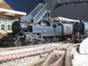
Bridge#1

This connects the Cynwyd branch with the two storage sidings that I set up when building the brewery……when complete I will have a low level roundy roundy.
Bridge #2
This is a Kibri kit that was a lot of fun to build…….never yet had trains running on it. It leads the mine exchange siding to a yet to be built storage siding that will become a low to high level roundy roundy. The plan is to run comparitively long (7'-8' ) 20+ wagon rakes of empty and full coal wagons…………20 is nothing compared with the prototype but hopefully I can create the desired effect. The substantial bridge will justify me using my 2 56xxs
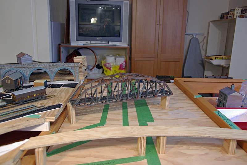
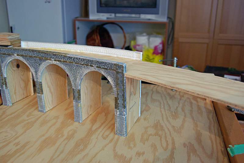
Bridge 3
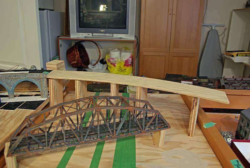
This is the viaduct another one of the key features on my must do list. This will connect the two road mainline exit from the storage yard with the terminus……giving me a third circuit this time at high level
I am struggling with the geometry of a curved viaduct……could be a problem
It also looks as though there may be an issue with the mine exchange running through the right hand viaduct pier but I think I will be able create a believable tunnel entrance.
As you must have gathered my broad brush approach is not totally compatible with detailed planning……if only!
I am going to use a Langley Kit for the viaduct
They dont have quite the definition of a Wills Kit but……big plus…..they are quite flexible
Bridge #4
Unlike the first three bridges there is no track laid on the right hand side……………the plan is to have a coal mine starting where the tape measure is and the siding (maybe two) over the bridge will connect with the coal roundy roundy by a kick back siding
Right now its a mock up so I can sort out the canal line
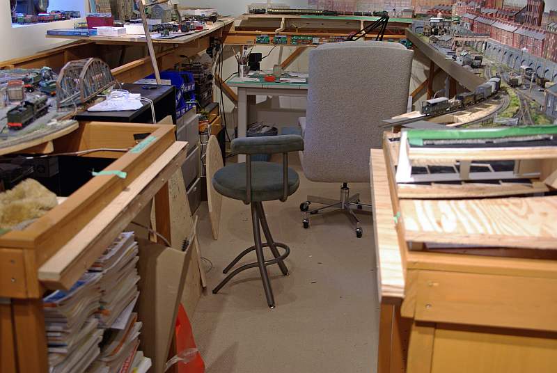
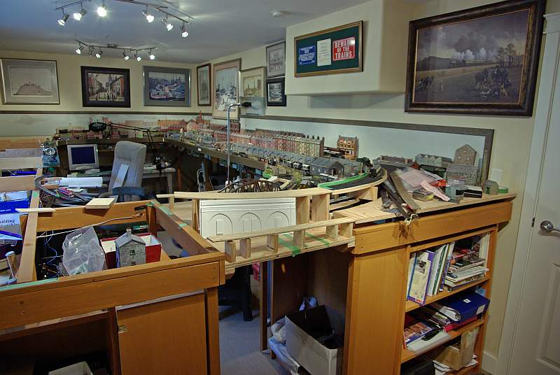
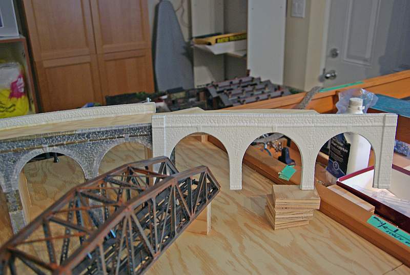
To finish here are a couple of shots which show how the main line will sweep (I hope) over the viaduct
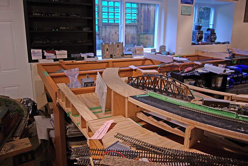
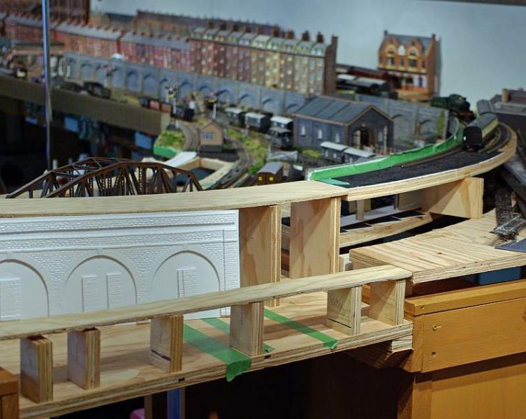
And finally an overall shot on an untidy railway room…………situation normal I am afraid!
Posted

Inactive Member
Max
Port Elderley
Port Elderley
Posted
Guest user
Posted
Guest user
as I am doing a curved viaduct too.
hope the back holds up to the duck-under..
 lol:
lol: :cool:
Posted

Full Member
Even in 'N' I had to plan for a canal basin. The curvature of the necessary bends on my canal won't hold up to slide rule scrutiny.
However, the narrow boats are easier to accommodate than scale sea going boats which are enormous.
Very interesting work - I look forward to updates but it's obviously going to be really something when finished.
Posted

Full Member
Cheers,John.B.:thumbs
Posted
Full Member
Not totally Sol I keep meeting the dog there and he is getting rather confusedThat duck under will keep you out of harms way for some time John.

Thanks for the encouraging comments guys. Here is an update on this weeks progress
One of the problems I had was determining where to start. I plan to create the canal by laying 1/4" ply on the baseboard to delineate the canal banks. Once this is done I am going to paint the revealed baseboard muddy brown and then apply n coats of varnish. However I dont fancy trying to insert the varnish brush that many times underneath 4 bridges but I cant layout the canal until the bridges are completed and I know precisely where the openings will be.
So I have decided to make the bridges as separate sub assemblies laid on the, as yet, uncut 1/4" ply.
Bridge 1 and 4 are already done and just need the openings for roads and the canal to be identified and additional supports inserted
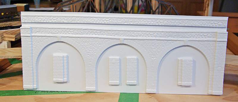
Bridge 3 the viaduct is the most critical structure because of the curve and the mine exchange line running under it
It was quite easy to cut out the formings and…..bonus day……not only do the pillars fit snugly around the 3/4" ply supports but I only needed to trim the bottom foundation course before mating it with the extension pieces

I believe I can mask the gaps with white glue and the raw edges will be sanded down. There is a moulding to cover the inside wall at track level. I have sheets similar to the viaduct stone work to clad the interior……….I am still debating whether I can get away with vertical faces and not worry about the arch itself
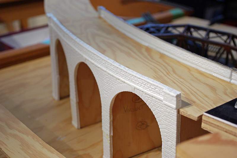
I am quite pleased with the curved effect. It was relatively easy to glue on. I just did 1 support at a time and gave it 24 hours to bond before going on to the next one
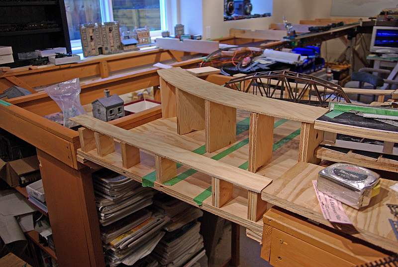
Geometry not being my strong suit it took a number of dry runs to convince me that setting each support at right angles wouldnt work. I finally remembered from my army days that when wheeling the outside file steps longer than the inside file:oops: The shot above shows how I have off set the outside support from the black covered baseboard……whereas on the other side, below, there is a much narrower gap
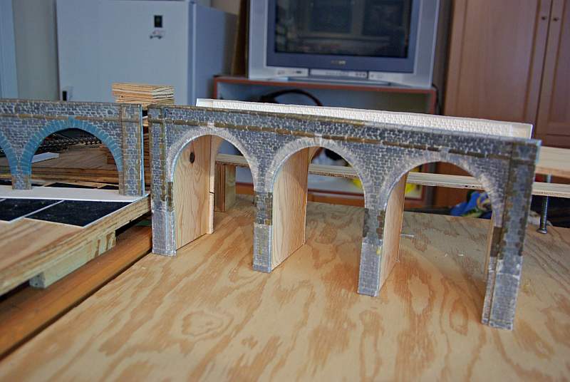
This shot gives a better illustration of the skewing effect……….its a good job the canal wasnt cut out because it is clear now it will have to somewhat curved…..which is no bad thing from an overall design aspect
The big problem I have is the impact the curve has on the straight run of the girder bridge
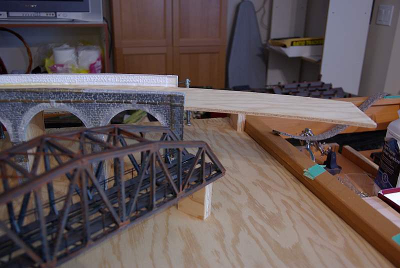
As you can see the line is going to enter arch 1 but, particularly when its starts to curve again (which it must)……it will have to exit on the other side through arch 2
I guess a compromise is to have a wider opening but I think that may spoil the effect……. right now I am thinking that instead of a solid support I will cut out an arch which the line can curve through ……anyway tomorrow I will cut out a 36" radius track bed to get from the end of the bridge to the edge of the duck under and then do some cardboard mock ups
If you can follow this convoluted explanation…..comments/ advice appreciated
Posted
Full Member
Don't forget the finger as a tool when painting stonework!
Posted
Guest user
Cant you run the curve from the girder bridge a bit to the left first from the end of the girder bridge then at some point swing the curve back to the right?
Brian
Posted
Guest user
it shows, try moving the bridge end to the right a little I think it will help.
it should then go through one arch only.???
 lol::cool:
Posted
Full Member
John
Cant you run the curve from the girder bridge a bit to the left first from the end of the girder bridge then at some point swing the curve back to the right?
Brian
Thanks Brian
I have tried that with short radius curves in an S shape but even that encroaches on the 10% of the room that is "common property"……….note the ironing board and freezer………..could be tricky :roll:
Posted
Full Member
John, it seems you have moved the angle of the bridge in your mock-up, going back over your pics
it shows, try moving the bridge end to the right a little I think it will help.
it should then go through one arch only.???
You are right…….. the bridge is now hard against the left hand baseboard with the fixed track……..it is also lined up more precisely with the fixed track.
I did this because it gave the "easiest approach"………..it was actually worse the other way. The skew effect of the supports is a lot more acute than I had appreciated. :hmm
Posted
Legacy Member
Different measurements apply to other types of canals but generally boat dimensions are common to all of them.
Richard. A sorely missed member who lost a brave battle in 2012.
Posted
Full Member
I was hoping to get some advice from you
That mean where the canal isnt going under a bridge its 30' wide…….I hadnt appreciated that although with all the bridges and the lock I guess I can stick at 8' and then go to 24/30' for the basin……provided the basin is at least 80' long?
How wide is the average Tow Path?
Kind Regards
Posted
Legacy Member
However the best way of deciding it is to remember the path was originally built for the horse to pull the boat so about the width of a horse would be about right - say 3 feet and most bridges have a path under them of about this width . A point worth remembering is that in the interest of security the towpath would not usually go into a basin but would stop at the boundary wall or a security gate . The basins would often have a bridge at this point and widen out from the bridge hole in a triangular shape to 70 feet in width as its possible to turn a boat in its own length . Not sure where you wish to put the lock but it would be the case that the canal would drop down to the terminus basin as if it were the other way round there would be water supply problems as the lock would drain the basin each time it was used. A lock by the way is usually 72 feet in length and 7ft 6" width.
Hope this helps.
PS. The 30ft width figure is a minimum on open canal stretches as it allows for boats to be moored on each bank and two boats able to pass each other between them. However on an approach to a basin or where there were a number of bridges and locks together it was not unknown to have stretches of canal only one boats width although it wasa nuisance from an operating point of view and would often lead to punch ups between crews as arguements over right of way got heated.
 Last edit: by Wheeltapper
Richard. A sorely missed member who lost a brave battle in 2012.
Posted
Full Member
Nor had I thought about the effect of a lock on the waterlevel of the basin
The Langley kit comes with one upstream gate and 2 x 1/2 downstream gates…………I had thought that rather than build a complete lock I would do 2 halves at each edge of the baseboard ie high level//basin level//low level that would create a more interesting scenario but I now realise somewhat unrealistic………………..could I create a pumphouse in the basin to keep the basin level ok?
1 guest and 0 members have just viewed this.