Granby Junction 1948 N. Wales
Posted

Full Member
GWR/LMS OO Gauge DCC RR&Co
[user=540]gdaysydney[/user] wrote:Hi DaveHi John,
Good to see you have bitten the bullet and are giving operating signals a try. It will give your layout and additional wow factor ( not that it needs one!)
Amongst my many signals I only have one semaphore signal which I hobbled together ten years ago. It was an old hornby metal signal and I rigged it up to a tortoise motor - no where near as realistic as the Dapol signals. This is the video I made as a prototype - experimentingLater I swapped the tortoise for a smaller ESU motor . You may need to design your own images for TC as a I recall at the time they didn't have any UK semaphore images in there selection. Its a while ago now and I don't recall how I did it but I am sure it will be no trouble for you. Both the motor set up and my semaphore graphic on TC are covered in a post back in August 2018
I will be watching with interest to see how you go and you may tempt me to install a dapol signal
Best wishes
Dave
Its hard to believe its 4 years since we had that conversation! I sure move at a snails pace.
I was trying to remember where I had seen a semaphore image to use in place of the TC light signal. Could you possibly send me the link - unless you have patented it

I must say watching the way TC handles the signal movement is a real pleasure and I am impressed with the Dapol product.
ps The "experimenting" link led me to your camera experiments - I didnt see the signal

Posted
Full Member
Aren't the posts supposed to be verticale John or is the cant a quirk of the GWR. ?

The signal movement is all done automatically.
One button click starts the schedule and thats it. Train Controller reserves the first block and the route to it. When the route is reserved the point is automatically thrown along with the associated signal arm. When the train clears the start block the signal is set back on and where appropriate the point returned to normal.
I must confess it is very satisfying after all this time.
My DCC voltage is 12.5-13v. Thats is perhaps why the lights look ok
We are beginning to create lists of lists. The current project is to recreate the the irrigation set up we had running in 2020 - Some gremlin (not I) re moved most of the labels so its a real guessing game :twisted:
Posted

Full Member
I will hunt through my files and see if I can get the grey matter working and send you what I have regarding the semaphore for TC. Just give me a few days.Hi Dave
Its hard to believe its 4 years since we had that conversation! I sure move at a snails pace.
I was trying to remember where I had seen a semaphore image to use in place of the TC light signal. Could you possibly send me the link - unless you have patented it
I must say watching the way TC handles the signal movement is a real pleasure and I am impressed with the Dapol product.
ps The "experimenting" link led me to your camera experiments - I didn't see the signal
Not sure what's happening to the link to the video. It was only 11 secs long but try as I might Youtube still insists on sending the link to the Cam Truck footage ( the cam truck gave up the ghost a few years ago now - I even tried a replacement lithium battery!) I have deleted the link from my original post so you will just have to image it
 Last edit: by gdaysydney
Posted
Full Member
Well it didnt take as long as I thought it would. File attached
Once you have set up the two aspect signals in TC click on edit image and import the file ( its zipped - I forgot the YMRC doesn't like unzipped files :oops:)
You can then edit the image to your liking -
Last edit: by gdaysydney
Posted
Full Member
Hi John,
Well it didnt take as long as I thought it would. File attached
Once you have set up the two aspect signals in TC click on edit image and import the file ( its zipped - I forgot the YMRC doesn't like unzipped files :oops:)
You can then edit the image to your liking -
Thanks Dave - that is brilliant

Posted
Full Member
Its now working beautifully in sync with the associated turnout. Train Controller activates it automatically. I can change it using the turnout procedure on the DCC Throttle or just click the icon on the screen - I even have a lower quadrant semaphore thanks to Dave @Gdaysydney

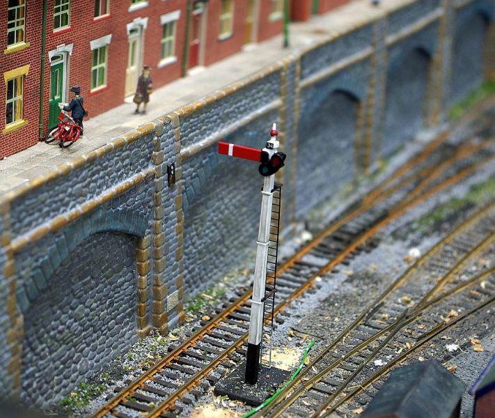
Here is a rather fuzzy shot showing the base duly painted to match the cess - thank you Mike The Stationmaster on RMWeb for putting me straight on that - and the sighting panel at work
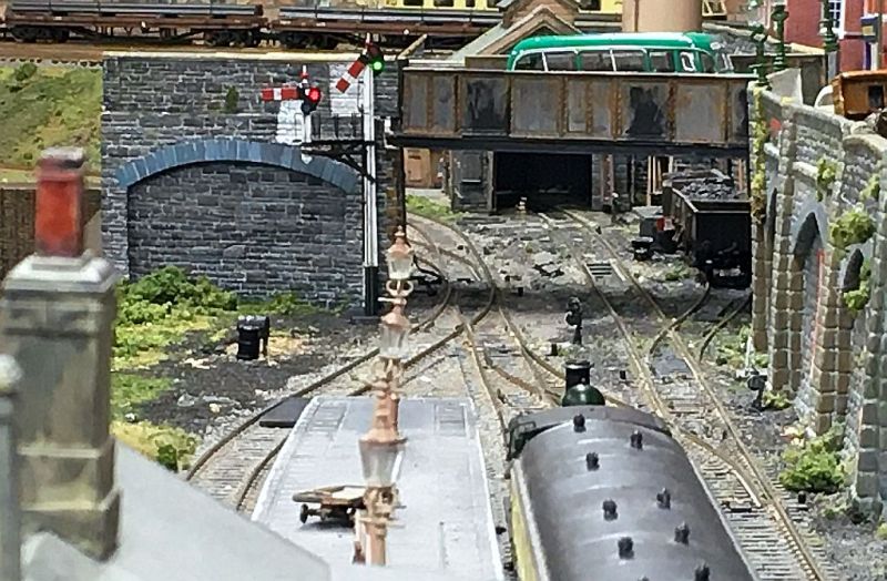
I am sorry about these shots. I had to use the iphone in an attempt to capture the driver's line of sight.
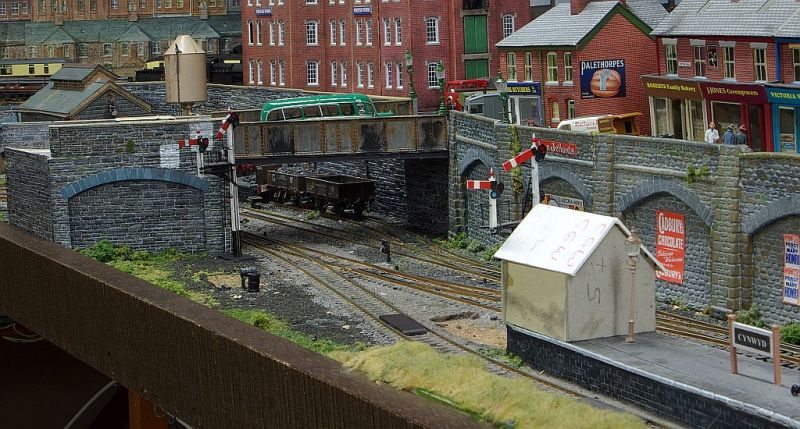
I have two related issues to resolve. Firstly the signal box which when put back in in it original position obscures the subsidiary arm:.
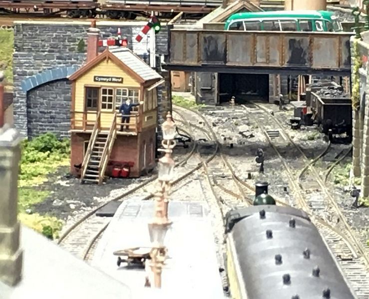
Option 1 is to move it further down the Bay:
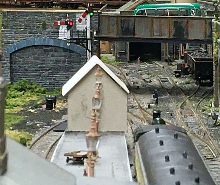
Option 2 is to remove the steps and lower portion and put it on the platform. Here is a card mock up:
Option 1 is preferable from a construction point of view but I suspect Option 2 is more prototypical for a smallish branch?
The second issue is providing starting signals for the bay and main line. Here is a mock up using an old Ratio bracket:
I worry that it is too close to the Junction signal? It could be located further back and embedded into the platform but this will restrict the Bay even more. Ideally I will add a siding signal at a later date to control exit from the loop. I suppose the alternative is cosmetic ground signals but I would really like to use a working signal linked to the turnout and junction signal.
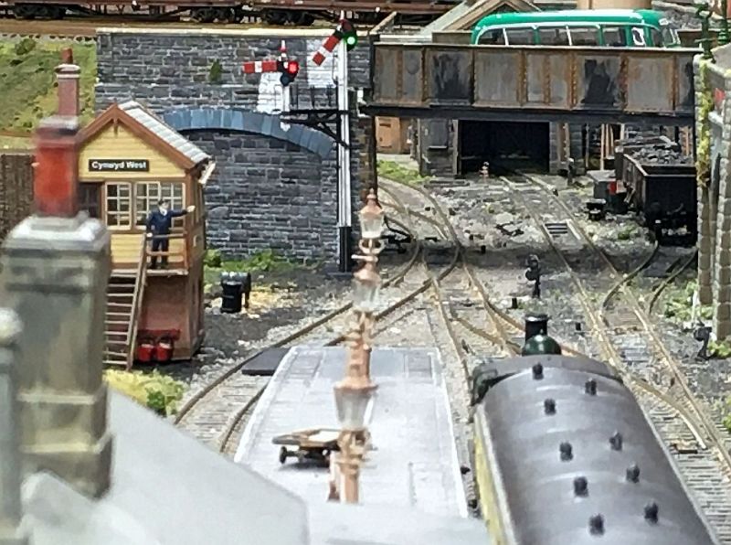
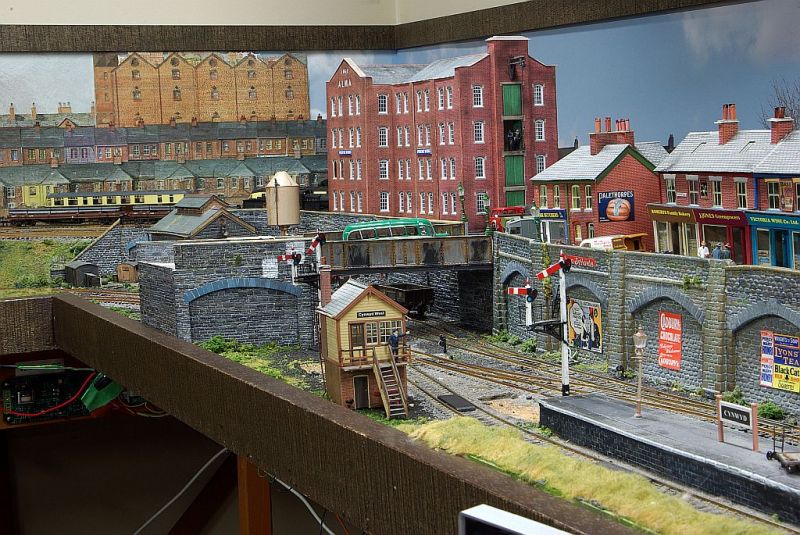
Here is a shot with the signal box on the platform, the lamp will be moved, the box can be placed further back and signal set into the platform.
And the option that involves less work but is, I suspect, less protot-typical
I am afraid none of these solutions is perfect. I am looking for the least worst option that combines working signals (which are in themselves a compromise) with a loose sense of realism.
Comments/suggestion will be much appreciated
Posted

Full Member
I know nothing about prototypical placement of signal boxes, but the last photo shows the nest visual and most interesting outcome.
Cheers,
Claus
www.flickr.com/photos/ellef/
Claus
www.flickr.com/photos/ellef/
Posted
Full Member
( that said if it was my layout I would go for option 1 as it is the easiest :oops:)
Posted
Full Member
Hi Claus - it looks like that is what I will be doing :thumbsHi John,
I know nothing about prototypical placement of signal boxes, but the last photo shows the nest visual and most interesting outcome.
Thank you for the feedback. By the time I have finished you will be an expert on GWR practice!
Posted
Full Member
Hi DaveOption 2 for me John - although it would mean the partial demolition of the signal box.
( that said if it was my layout I would go for option 1 as it is the easiest :oops:)
Looks like you are in a minority. The guys on RMWeb where all very much in favour of Option 1. :roll:
I actually had the same thoughts as you that modifying the box and putting it on the platform was the " correct" option. I am more than happy to be persuaded otherwise - as you say it saves me a load of work and I have the seal of approval.
Furthermore Mike (The Stationmaster) who is very knowledgeable and super helpful reminded me about "Local Instructions" so I dont need to be so concerned about the exact location of the starter.
Posted
Full Member
Nice work.
Cheers Pete.
Posted

Full Member
Great work on all fronts, both modelling and programming John. It must be very satisfying having the signals linked to the points with RR&Co. I think I may be able to do it with the second set of switch contacts on the Tortoise motor.
Sorry for not posting sooner, as we’ve had clients and numerous visitors since June, with little time for following the railway forums :sad:, although I’m eagerly waiting to see the Hornby magazine video on the Accurascale sound fitted Manor tomorrow :cool:
Glad to see you have closure for the signal box location and can now finish the installation and develop your schedules. Might there be a video in the wings?
Best,
Bill
At 6'4'', Bill is a tall chap, then again, when horizontal he is rather long and people often used to trip over him! . . . and so a nickname was born :)
Posted
Full Member
Hi BillHi John,
Great work on all fronts, both modelling and programming John. It must be very satisfying having the signals linked to the points with RR&Co. I think I may be able to do it with the second set of switch contacts on the Tortoise motor.
Sorry for not posting sooner, as we’ve had clients and numerous visitors since June, with little time for following the railway forums :sad:, although I’m eagerly waiting to see the Hornby magazine video on the Accurascale sound fitted Manor tomorrow :cool:
Glad to see you have closure for the signal box location and can now finish the installation and develop your schedules. Might there be a video in the wings?
Best,
Bill
Good to hear from you. No question summertime can interfere with modelling. I am not running anything like as many trains as I would wish!
I am delighted I appear to have resolved my signalling issues. I got myself in a right bind with my bench work construction, track layout and the constraints of the Dapol Bracket Signal. I am very lucky to know such a helpful bunch of experts. I admit it is very satisfying watching the turnout blade moving, followed by the signal arm dropping and the train slowly pulling out of the platform and then watching blade and arm return to normal when the train has cleared the platform.
With the trial completed and issues resolved I am just awaiting delivery of some more bracket signals and I now need to order 3 pole signals to complete the branch signalling. Made quite a hole in the Railway Budget so although like you I am looking forward to Friday and the Manor reveal I am quite relieved their delivery date has been put back to Q3/4
A video is indeed planned but it will be late fall at the earliest
Best
Posted

Full Member
Impressive work with the signal - it adds yet more realism to Granby (if that were possible :roll:)
Shots like these give me further opportunity to examine parts of the layout in close up detail. More please !!! :doublethumb
'Petermac
Posted
Full Member
Hi PeterFor me John - no contest re the signal box placing - non-prototypical or not, option 1 is by far the most attractive, even if the cardboard mock-up were a real box !!
Impressive work with the signal - it adds yet more realism to Granby (if that were possible :roll:)
Shots like these give me further opportunity to examine parts of the layout in close up detail. More please !!! :doublethumb
Option 2 didnt get too many votes - it may have bee my rather crude mock up put people off . :roll:
Much of the scenery on the branch is 12+ years old - its "naturally" weathered
but now heavily scarred with the removal of all the cosmetic signals and the construction mess from installing the new ones. Blending in the replacement ballast and grass is unlikely to be seamless :sad:I have three brackets installed - two to go - right now I am waiting for some Dapol single posts from Hattons. Progress seems painfully slow - gardening keeps intervening! :sad:
John
Posted
Full Member
Cheers Pete.
Posted

Full Member
Well, mine's finished :roll:. Just been sharpening the chain saw for the "off". Farewell W-HNo it wasn't the mock up, it just looks so much better where it's ended up. It's said that a layout's never finished but yours must be close.

Colin
Posted
Full Member
Cheers Pete.
Posted
Full Member
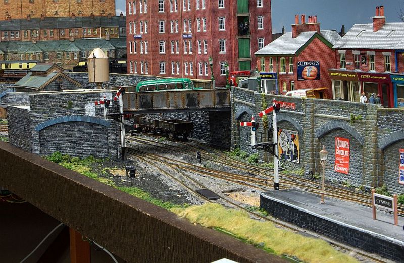
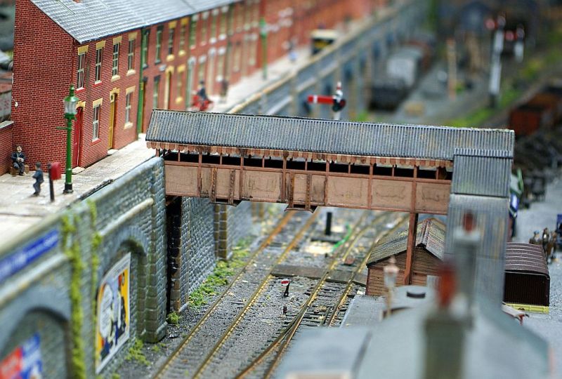
I left you in early July with this:
A Dapol bracket signal installed for the junction ( just beyond the bridge) and unanswered questions about the best location of the Up Starters for both the running line and bay.
After much procrastination, I decided that the best solution was to use two separate poles, rather than installing a second bracket. Further research allayed my doubts about the reliability of the Dapol single pole version. I also need a Down Starter so three were ordered along with two Train Tech DCC signal decoders.
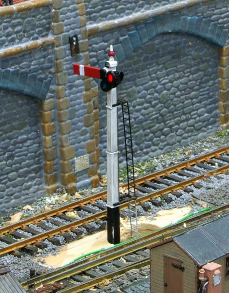
Installation was simple - unlike the brackets there is no obtrusive power box. Here is the Down Starter:
Sadly the white stripe on the board is distinctly under-nourished!
On the other hand the pole is a scale 24' long - standard length for a Home signal but not for a Starter where 16' or less was more usual. Certainly what was needed at Cynwyd where the sight line to the full length pole is obscured by the footbridge::

and the solution:
I felt shortening the pole and ladder was likely to damge the movement mechanism. Instead I drilled a second larger hole, inserted the signal from under the baseboard and a glued the edge of the signal base to the baseboard.
(thank you for the suggestion Colin)
Crude but effective:
Its actually a scale 18' high but I am not going to get too excited over 8mm.
Beforehand I painted the "new" base of the pole black and adjusted the white paint at the foot of the ladder. I also widened the white stripe on the board and the matching black stripe on the reverse.
Similar treatment for the Up starters :
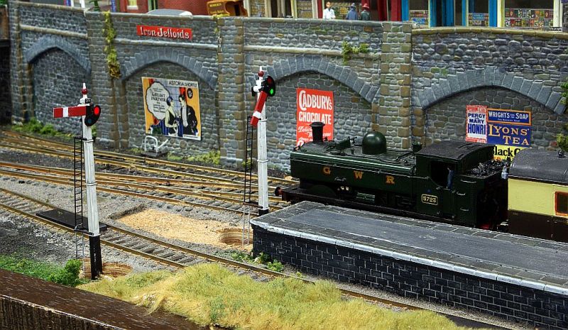
I must say that my initial misgivings about the operation of the Dapol single poles were misplaced. Admittedly, the mechanism is rather noisy and they dont have the "bounce" seen on the bracket signals. Having said that, they have proved to be reliable over quite extensive testing and required none of the fiddly adjustments needed for a couple of the bracket signals.

I cant quite say "all finished" - I have to replace the Signal Box and Water Crane and of course there are three overlarge excavation pits to be concealed.
Remaining with Dapol - I eventually succumbed to the many favourable reviews of their new Manor - Compton Manor is currently winging its way from the Mersey to the Pacific - more to come when it arrives.
In other news our Taiwanese rescue Mutt is very territorial and determined to protect us at all costs. However his unsuccessful attempt to catch a skunk was decidely ill-advised!
Best wishes from a still evil smelling part of Vancouver
Posted
Full Member
Skunk chaser eh. I bet it's really nice round your place at the moment.
Cheers Pete.
1 guest and 0 members have just viewed this.