Granby Junction 1948 N. Wales
Posted

Full Member
GWR/LMS OO Gauge DCC RR&Co
Wow that was quick Colin - glad you likeI had to do swift checkback on the photo selection with the neighbours comment. The other side of the room is, indeed, overlooked by our neighbours - then the penny dropped!
Best

Posted

Full Member
One advantage of our being 17 hours "ahead" of you there. My essential early morning reading.Wow that was quick Colin - glad you like
I had to do swift checkback on the photo selection with the neighbours comment. The other side of the room is, indeed, overlooked by our neighbours - then the penny dropped!
Best
BTW I was talking about the "neighbours" in the terraces behind the sidings now they have trains right up close.
Colin
 Last edit: by Colin W
Posted
Full Member

I doubt if I could construct Ratio's manual working mechanism but even if I could it would be pretty meaningless on a layout operated by RR&Co.
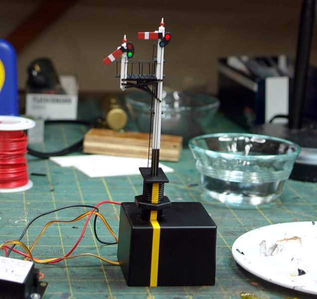
This automated junction signal from Dapol has had good reviews:
Its a close enough representation of a GWR lower quadrant and it can be hooked up to a DCC accessory decoder and thence linked to RR&Co's Train Controller.
The major downside - apart from the cost, which is not insignificant, - is the amount of below baseboard clearance that is required. Furthermore, as I know all too well, retrofits that require drilling a 15 mm (5/8') through the baseboard can have adverse, un-planned side-effects!
"Nec aspera terrent" as we used to say in the Kings Liverpool Regiment - Difficulties be damned!
Two sets have been purchased for a trial installation on the branch :
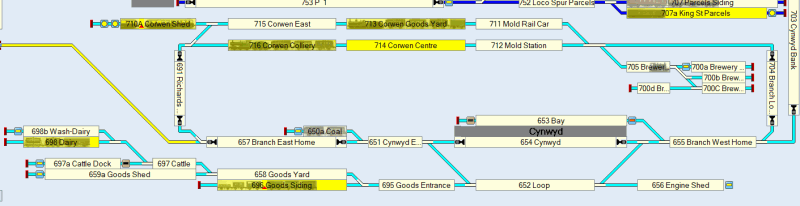
Initial thoughts are to have the first unit as a starter for exiting either the bay or the main platform. (Exit from the loop will continue to be with a cosmetic ground signal.
The second unit will control the junction where the line goes past the brewery to the hidden storage (Mold) or climbs Cynwyd Bank to Granby
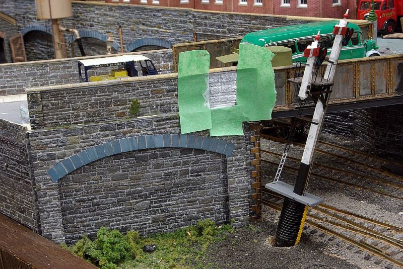
This shot shows the existing cosmetic starters:
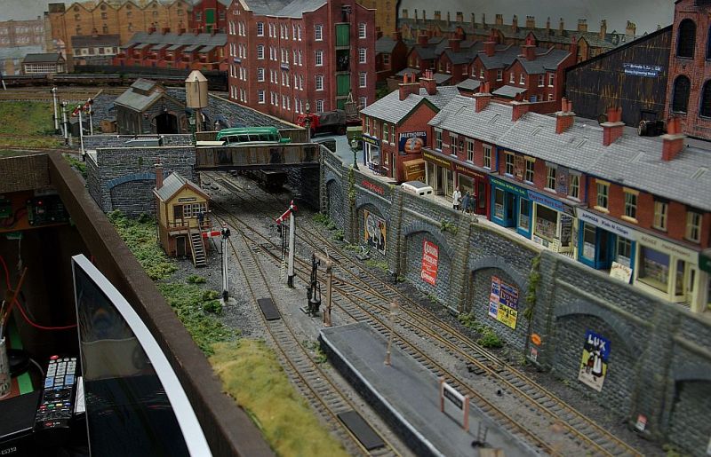
It also exposes one of my many faux pas. Not the bus - there are special circumstances for that!
The error is the positioning of the Junction signals beyond the bridge - where they can barely be seen,if at all, from the station side.
To make it even worse, both signals are placed well beyond the turnout they are controlling :oops:
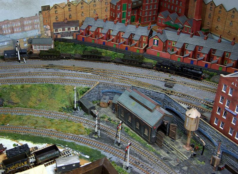
The bridge is almost immediately above the turn out! It actually conceals the turnout motor. I did think of re siting the bridge but it is too complicated.
The plan is to move the Signal Box and place the Junction Signal as close as practicable to the bridge. I will probably need to add a sighting board behind.
I originally planned to re locate the Water Crane and place the Starters signal immediately in front of the platform but I think that will be too close to the new junction signal. So Plan B is to actually embed it in the platform - that should be fun - but I have seen this done on two layouts that I admire.
Ground is yet to be broken or more accurately ply wood has not yet been drilled- so any ideas, suggestions or comments would be more than welcome. Nec aspera terrent is all very well but I think this particular project calls for a rather cautious approach.
Regards from Vancouver where we are enjoying a combination of showers and temperature approaching 20o -great growing weather
Posted

Full Member
Hi John,Great getting news from Granby. Unfortunately I know nothing about GWR signalling, but I will still follow your progress.I have always been somewhat embarrassed about the signalling on Granby. Technically, it is less than perfect but my principal objection is the fact that there is only one working signal on the entire layout - a fixed distant
I doubt if I could construct Ratio's manual working mechanism but even if I could it would be pretty meaningless on a layout operated by RR&Co.
This automated junction signal from Dapol has had good reviews:
Its a close enough representation of a GWR lower quadrant and it can be hooked up to a DCC accessory decoder and thence linked to RR&Co's Train Controller.
The major downside - apart from the cost, which is not insignificant, - is the amount of below baseboard clearance that is required. Furthermore, as I know all too well, retrofits that require drilling a 15 mm (5/8') through the baseboard can have adverse, un-planned side-effects!
"Nec aspera terrent" as we used to say in the Kings Liverpool Regiment - Difficulties be damned!
Two sets have been purchased for a trial installation on the branch :
Initial thoughts are to have the first unit as a starter for exiting either the bay or the main platform. (Exit from the loop will continue to be with a cosmetic ground signal.
The second unit will control the junction where the line goes past the brewery to the hidden storage (Mold) or climbs Cynwyd Bank to Granby
This shot shows the existing cosmetic starters:
It also exposes one of my many faux pas. Not the bus - there are special circumstances for that!
The error is the positioning of the Junction signals beyond the bridge - where they can barely be seen,if at all, from the station side.
To make it even worse, both signals are placed well beyond the turnout they are controlling :oops:
The bridge is almost immediately above the turn out! It actually conceals the turnout motor. I did think of re siting the bridge but it is too complicated.
The plan is to move the Signal Box and place the Junction Signal as close as practicable to the bridge. I will probably need to add a sighting board behind.
I originally planned to re locate the Water Crane and place the Starters signal immediately in front of the platform but I think that will be too close to the new junction signal. So Plan B is to actually embed it in the platform - that should be fun - but I have seen this done on two layouts that I admire.
Ground is yet to be broken or more accurately ply wood has not yet been drilled- so any ideas, suggestions or comments would be more than welcome. Nec aspera terrent is all very well but I think this particular project calls for a rather cautious approach.
Regards from Vancouver where we are enjoying a combination of showers and temperature approaching 20o -great growing weather
Cheers,
Claus
www.flickr.com/photos/ellef/
Claus
www.flickr.com/photos/ellef/
Posted

Full Member
Following along with interest.
Best,
Bill
At 6'4'', Bill is a tall chap, then again, when horizontal he is rather long and people often used to trip over him! . . . and so a nickname was born :)
Posted

Full Member
Michael
Posted

Full Member
As Michael said, signalling is even more of a dark art than electronics John but, looking at your new signal, you're going to have to excavate a fair old hole in the baseboard to accomodate that huge box - or do they separate for installation then re-join via a smaller hole ……………. :hmm
Semaphore signals are very attractive (I think) and add greatly to the realism of a layout. On the other hand, learning their correct placement and operation is way beyond my feeble mind……………………. :oops:
For a bit of fun (and soldering practice), I've purchased an MSE LNER lattice post signal kit to see how I get on with it then, if it looks half decent, it may find it's way onto Maxmill to be operated by a servo motor - but that won't be today …….. ;-)
Really looking forward to learning something about this mysterious subject via Granby posts. :thumbs
Incidentally, many thanks for drip-feeding my hunger for photos of Granby - more superb shots for me to pore over. :cheers
'Petermac
Posted

Full Member
Interesting challenge. The GWR would probably have used a small gantry and avoided the issues of complex rodding. And maybe even used search light signals (which they were using from the 1930s).
Repeater signals in the form of ground signals or short platform signals were also used when sightlines from the locomotive were blocked. Which begs the question - are the sightlines from the signal box to the signals OK? The signals should be visible from the box not just the locomotive to confirm they changed. One of the reasons for those elevated signal boxes found in various locations, usually erected when a new set of points was installed beyond a bridge.
The black art of signalling, usually associated with cans of worms.
Nigel
©Nigel C. Phillips
Posted
Full Member
Hi ClausHi John,Great getting news from Granby. Unfortunately I know nothing about GWR signalling, but I will still follow your progress.
Good to hear from you.The GWR took pride in doing things a little differently from everyone else. When it came to signalling they had an array of unique minor signals - "backing arm" for instance but the principal difference between them and the rest of the big four was their continued use of the lower quadrant ie when the signal was "off" ie the road was clear the arm dropped from the horizontal stop position to an angle of 45o. The other railway companies raised the arm to a 45o position (upper quadrant) when the signal was off.
Best wishes
Posted
Full Member
Hi BillYou're as brave as ever John and I hope, if absolutely necessary, the gubbins underneath can be fettled as may be required.
Following along with interest.
Best,
Bill
I hope you are keeping well?
I had hoped to be learning from you - but it looks as though I will be breaking ground first! I dont think the installation itself is too much of a challenge. From everything I have read these 2nd generation bracket signals are very much plug and play and have none of the voltage issues that plagued the initial release of single pole signals.
My challenge is retrofitting with all manner of less than neat cable runs cluttering the underside of the baseboards. The open girder framework I use is an added complication because the front girder is, of course, blocking the best location for two of the proposed signals!
I am not looking forward to cutting out the platform - I may have second thoughts there - but I believe I have a pretty clear site for the junction signal. Hopefully I will shortly be able to post some "in progress" shots.
Best wishes
Posted
Full Member
Thank you Michael, that is very kind of you.Like many things in this this wonderful hobby, signalling seems to be one of those dark arts to the un-initiated like myself. So your cosmetic signals, even if incorrectly placed, have always given me the impression of a working railway at Granby. That said, I can well understand your desire to try to get it right (after all, you don't want to actually finish, do you?) and to add some automation. So I will be following along and making a note of things for when I get to that stage on the Kent Coast. Always a pleasure reading your updates.
Michael
Railway Signalling is a truly fascinating subject. I think of it as the sinews or better still, nervous system of the railways. I dont think a model railway can be considered complete without some a semblance of a signalling system although more often than not the signals will be cosmetic. I will never attempt, for instance, to make the signals operational on Granby's gantry. However it is difficult to resist the temptation of installing an accurate and reliable working signal to control the points leading to the branch station.
When you get to the stage of installing signals (working or cosmetic) on the Kent Coast you may find C.J. Freezer's "Model Railway Signalling" * useful. I found it invaluable. It covers both Semaphore and Coloured light signalling in some depth, it is by no means confined to the GWR. It gave me a rudimentary understanding of block practice which provided a foundation for understanding this "dark art".
* I dont know whether it is still in print - it was originally published by Patrick Stephens Limited in 1991. One of my most well thumbed reference books. Well worth searching for.
Best Wishes
Posted
Full Member
Hi PeterYou're a braver man than I Gunga Din ……………….. :roll:
As Michael said, signalling is even more of a dark art than electronics John but, looking at your new signal, you're going to have to excavate a fair old hole in the baseboard to accomodate that huge box - or do they separate for installation then re-join via a smaller hole ……………. :hmm
Semaphore signals are very attractive (I think) and add greatly to the realism of a layout. On the other hand, learning their correct placement and operation is way beyond my feeble mind……………………. :oops:
For a bit of fun (and soldering practice), I've purchased an MSE LNER lattice post signal kit to see how I get on with it then, if it looks half decent, it may find it's way onto Maxmill to be operated by a servo motor - but that won't be today …….. ;-)
Really looking forward to learning something about this mysterious subject via Granby posts. :thumbs
Incidentally, many thanks for drip-feeding my hunger for photos of Granby - more superb shots for me to pore over. :cheers
I just have to drill a 5/8" aperture. The bulky oblong electronic gubbins is literally an appendage which clips on underneath after the post has been inserted in the hole and secured using the knurled nut that can be seen just above the electronic box. Clearance for the box is still an issue because of the open frame girder that runs about 9" back from the edging board. Believe me, there will be a great deal of testing before the drill bit touches wood!
Signalling isnt really such a dark art and I think you will enjoy learning about the logic that governs both the type of signal and its positioning. You may want to consider leaving my post to Michael where Liz can read it. CJ Freezer's book, "Model Railway Signalling" would make the perfect Christmas present!
Best wishes
Posted
Full Member
Hi NigelHi John,
Interesting challenge. The GWR would probably have used a small gantry and avoided the issues of complex rodding. And maybe even used search light signals (which they were using from the 1930s).
Repeater signals in the form of ground signals or short platform signals were also used when sightlines from the locomotive were blocked. Which begs the question - are the sightlines from the signal box to the signals OK? The signals should be visible from the box not just the locomotive to confirm they changed. One of the reasons for those elevated signal boxes found in various locations, usually erected when a new set of points was installed beyond a bridge.
The black art of signalling, usually associated with cans of worms.
Nigel
Nice to hear from you and thank you for your comments.
As it happens I will be using bracket signals, although largely for ease of use rather than proto-typical accuracy :oops:.
Not sure how familiar you are with the Dapol Junction Signal Range? They are quite versatile with a choice of either Left or Right principal arm or a single arm, again Left or Right. Apart from being reasonably accurate the big attraction to me is their reputation for reliable operation- I know my limitations when it comes to practical mechanics with small objects. I can hook these up to Train Tech's purpose designed signal controller and this in turn is connected to the DCC bus - one of the few cases where it is just two wires
- and thence to a mimic signal icon on the RR&Co switchboard. The signals will be controlled with the associated turnout and subject to appropriate customised conditions.That is a good point you raise about visibility from the signal box and another argument in favour of locating the junction signal on the station side of the bridge. Unfortunately that raises the issue of the Junction signal for the opposite direction ie trains approaching rather than departing from the station. :shock: It will have to be on the far side of the bridge and therefore out of sight of the box! I guess I will have to come up with a plausible explanation I dont believe I can raise the box…….problems problems ….one of the charms of the hobby.!
Best Wishes
Posted
Full Member
Please excuse my DDC ignorance, but what voltage does your DCC bus run? My NCE unit supplies 15v and the earlier Dapol instructions incorrectly advised a 16v supply which fried the motors, so I’ll feed mine from a 12v accessory bus, which accords with Dapol’s latest advice. (Thanks to Nick Wood for that, who learned the hard way)
I’m sure you’ll pick this up from the instructions, but I’d hate to hear you’d had an unexpected cooked breakfast if I’d said nothing!
You’ll be getting plenty of advice here and there, so it should work its way out well and you will have a respectably prototypical system for the branch.
I’m still making my way through various signalling books when I find some time and despite all normal standards set out by the company, unusual circumstances of visibility resulted in the safest solution being adopted for placement, despite the rules. Signals could often be seen on both sides of the running lines on the GWR for example.
Still following along with interest.
Best,
Bill
At 6'4'', Bill is a tall chap, then again, when horizontal he is rather long and people often used to trip over him! . . . and so a nickname was born :)
Posted
Full Member
Thanks for the heads up Bill. I believe the voltage issue arose with the first generation single post signals. One of the reasons why I am confining myself to using the second generation junction signals.Dapol instructions for these state it can be powered by DCC track voltage up to 18v. Granby's bus is 12-13vHi John,
Please excuse my DDC ignorance, but what voltage does your DCC bus run? My NCE unit supplies 15v and the earlier Dapol instructions incorrectly advised a 16v supply which fried the motors, so I’ll feed mine from a 12v accessory bus, which accords with Dapol’s latest advice. (Thanks to Nick Wood for that, who learned the hard way)
I’m sure you’ll pick this up from the instructions, but I’d hate to hear you’d had an unexpected cooked breakfast if I’d said nothing!
You’ll be getting plenty of advice here and there, so it should work its way out well and you will have a respectably prototypical system for the branch.
I’m still making my way through various signalling books when I find some time and despite all normal standards set out by the company, unusual circumstances of visibility resulted in the safest solution being adopted for placement, despite the rules. Signals could often be seen on both sides of the running lines on the GWR for example.
Still following along with interest.
Best,
Bill
The feed from the track (ie nearest droppers) goes to the Train Tech controller and then on to the signal itself.
Assuming the trial is successful, I will be using the "both sides" precedent when placing two more junction signals :)
Best Wishes
Posted
Full Member
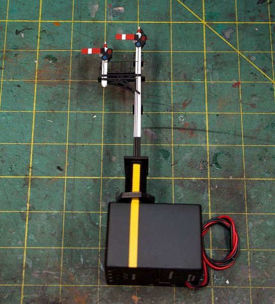
I finally found the time to start installing the Junction bracket signal.
First job was to check the lighting:
The wiring is very simple. Red and Black provide the power - in my case direct from the DCC track.
The two signals are each already connection to a SPDT switch so it really is a case of plug and play test.
I want to connect the signals to the RR&Co software so I removed the supplied switches and connected them to a SC4 decoder from Train-Tech :
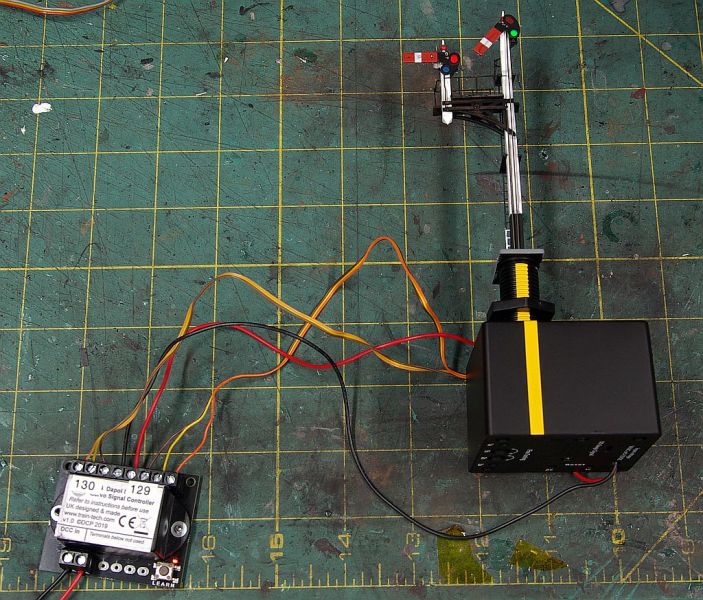
It works just like a point decoder. I can operate the signal either from the DCC throttle or the computor screen. With RR&Co it is linked to the turn out it protects and is automatically activated whenever a route is set.
There have been comments from some users that the light is too bright. The intensity is dependent on the voltage input so it looks as though I have been lucky.
When testing the signal movement the main (RH) arm worked perfectly straight out of the box with a realistic and rather satisfying "bounce" effect when the arm returned to "On".
The subsidiary (LH) arm initially failed to return to the horizontal when switched "On". I was able to solve this issue using the controls in the base of the power unit:

Before actually installing the unit I wanted to tone down the pristine finish (definitely not Granby's style).
The platform was painted brown/grey, the rails/ladder dry brushed with touches of rust, the base of the ladder painted white and the black base concrete. Finally a light wash of very diluted dirty black.


Finally the moment of truth, time to drill using the supplied template (Dapol's instructions were excellent):
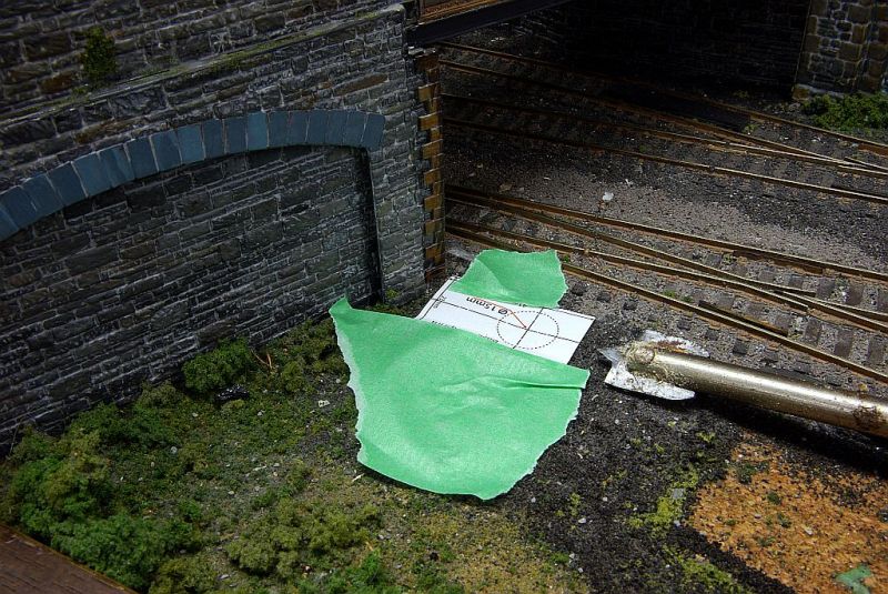
Why the concern?
The baseboards are mounted on L Joists. The front joist is set back about 6" from the edge of the baseboard. The power base unit has a substantial footprint. To add to this sense of jeopardy the joist carries 15 years of wiring and assorted decoders. What could possibly go wrong?
Well the deed is done. I got so excited I forgot to to take a photo.
So here we see the signal resting in its hole while I wait for the paint on the main sighting panel to dry!
The sharp eyed will notice that Wynn's lorry driver (top right) became so alarmed - he fainted.
To be continued
Posted
Full Member
I see from the photo of the base there are fine controls and resets, are these explained in the contained instructions? Their website doesn't seem to cover the double arm variant of the model.
Colin
Posted

Full Member
Good to see you have bitten the bullet and are giving operating signals a try. It will give your layout and additional wow factor ( not that it needs one!)
Amongst my many signals I only have one semaphore signal which I hobbled together ten years ago. It was an old hornby metal signal and I rigged it up to a tortoise motor - no where near as realistic as the Dapol signals. Later I swapped the tortoise for a smaller ESU motor . You may need to design your own images for TC as a I recall at the time they didn't have any UK semaphore images in there selection. Its a while ago now and I don't recall how I did it but I am sure it will be no trouble for you. Both the motor set up and my semaphore graphic on TC are covered in a post back in August 2018
I will be watching with interest to see how you go and you may tempt me to install a dapol signal
Best wishes
Dave
Last edit: by gdaysydney
Posted
Full Member
It's a great looking signal John. Will it work automatically when you set the route Vis RR&Co or will you have to be quick off the mark. You mentioned the light intensity which, in your case, looks ideal. I presume your DCC voltage is around 15v …. :roll:
Like you, summer is not the best time for modelling - no matter how hard I try to set time aside, something unforseen always crops up - usually under the guise of "Liz's List"……
'Petermac
Posted
Full Member
Thanks Colin - glad it was food for thought.Very Interesting John, you've really caught my attention now.
I see from the photo of the base there are fine controls and resets, are these explained in the contained instructions? Their website doesn't seem to cover the double arm variant of the model.
Colin
The instructions for the bracket signals are very comprehensive and cover the tuning procedure. Basically you can adjust the movement of each signal arm and if you screw up (as I did) you can re set to factory settings
1 guest and 0 members have just viewed this.