Going Small with a GWR Branchline 1890-1920
Posted

Full Member
GWR Branchline in EM Gauge 4mm Scale
Hi Peter,Thanks. Many 3D prints come only in nylon, which is inert. Belt and braces approach after my previous experiences with various 3D print materials and styrene. Good keying helps by increasing surface area and cavities. Needs gap-filling CA as well.
The Canada goose and it's mate were looking for empty plant containers to nest in as all the best sites around the lake are taken. Lots of honking from this one as it's mate reckoned the one next door was better (it had a plant pot with soil, ours has a hole). How they get the goslings down after hatching is a mystery.
Nigel
©Nigel C. Phillips

Posted
Full Member
Some more work on the GWR autocoach/trailer as well as the 6-wheeler brake third coach today.
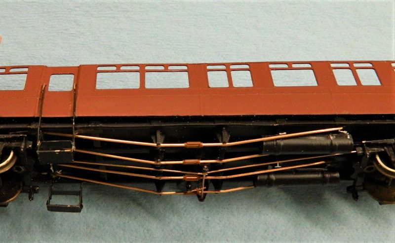
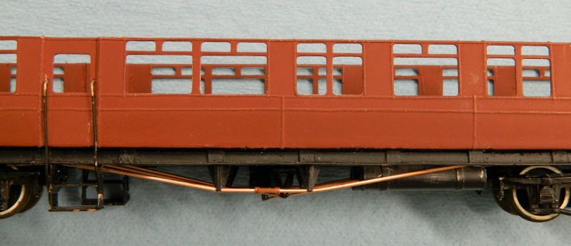
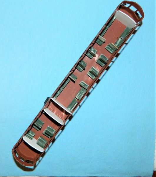
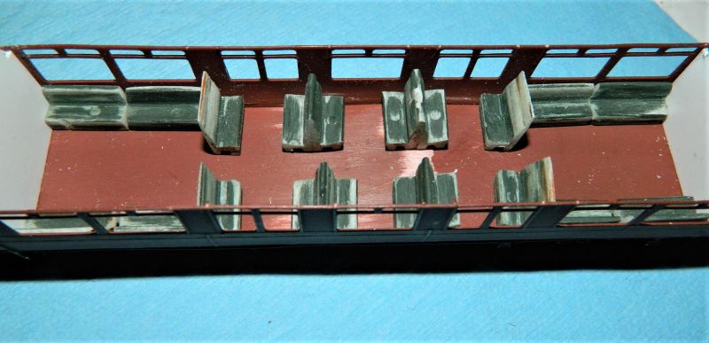
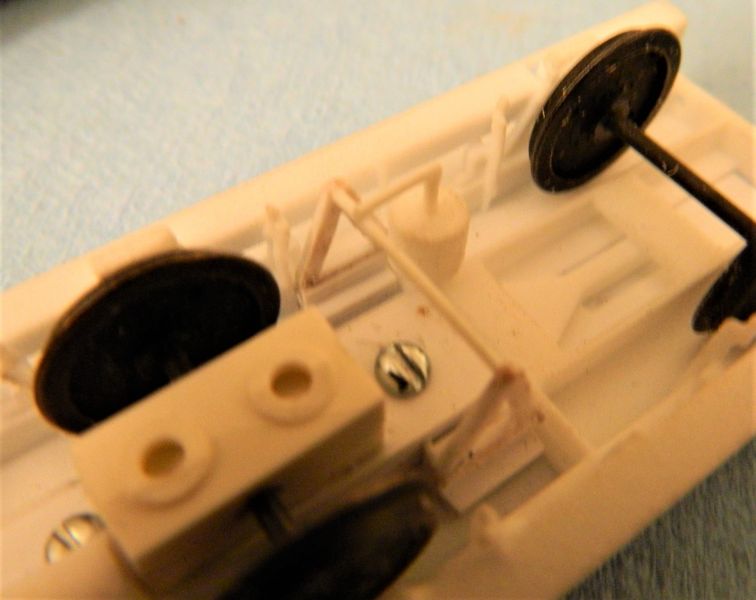
The coach underframe now has tension rods (4 in total) and turnbuckles, rudimentary brake rods, refurbished steps, coach partitions (which will need a lot of further work, as the real thing had pocket doors), and cleaned-up seating. The seating used by the previous builder looks suspiciously like HO seating, definitely under-scale compared with the diagrams, with way too much space between the seats. It looks like some new ones with a bit more thigh support are needed. That or HO scale people! I have a couple of packs of Ratio seating in the spares, so we'll see what that looks like. The real things had seats with legs and wooden arm rests, not sure about that given the number required.
The 6-wheeler chassis came with a basic vacuum cylinder, it now has a connecting lever, scratch built V-hangers and rod. Plus of course a gas cylinder. The roof has also been detailed (no photos yet). Gas lamp hoods, basic piping supply, a few ventilators and a rail channel either side. Seating for the passengers along with partitions have also been made.
Layout construction is currently on hold pending a decision about moving in the late fall to a house (with basement or spare room). What we are looking for usually comes with a full basement (around 30 x 40 feet), and an acre or three of land, outdoors is a distinct possibility. I shall continue to build the stock and points and of course the buildings.
Nigel
©Nigel C. Phillips
Posted
Full Member
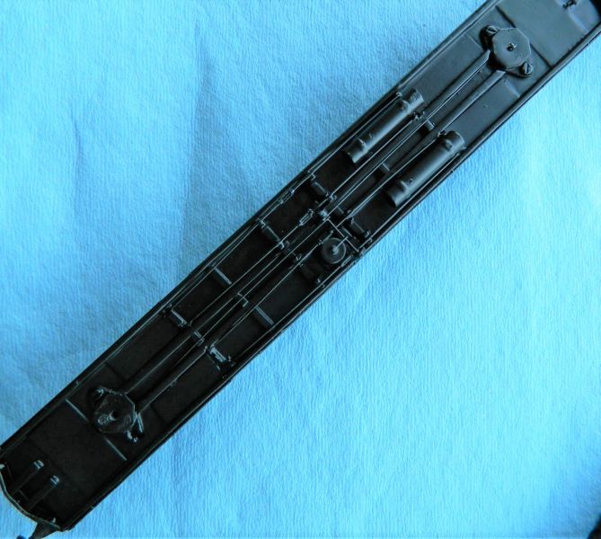
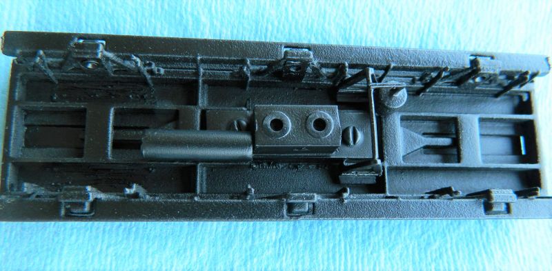
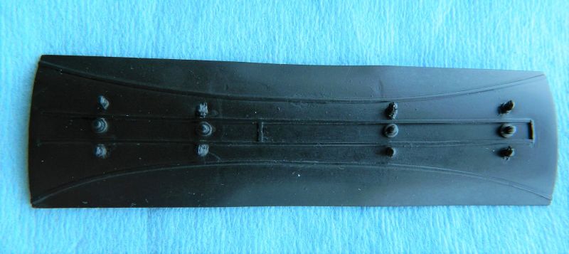
Rattle can black paint/primer time. Autocoach underframe, 6-wheeler underframe, and the roof for the 6-wheeler.
Nigel

©Nigel C. Phillips
Posted

Full Member
A couple of questions - do you mask off the bodywork when spraying the black or is the bodywork removed and secondly, do you cover the bearing sockets (pin point or otherwise) when spraying or clean them afterwards ?
'Petermac
Posted
Full Member
No masking tape for both. The autocoach is now in black Krylon primer/paint, matt), given that the top coat is going to be crimson lake (or as closed as I can get with a rattle can). it will be easier to mask the chassis rather than the body. Axle bearings. I just use a pinpoint bearing reamer to gently clean them out. Faster than messing around with tape.
Nigel
©Nigel C. Phillips
Posted
Full Member
'Petermac
Posted

Full Member
Michael
Posted
Full Member
Thanks. It's getting reasonably close to what I want. That said, the plan calls for a matchstick autotrailer, not a paneled one. Hey ho…
Nigel
©Nigel C. Phillips
Posted
Full Member
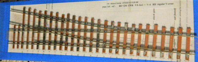
I finally made a start on the remaining points (turnouts) over the weekend. The first was first one is immediately after the exit turnout to the yard from the branchline (the "spare" siding). I used an asymmetrical wye (for want of a better definition) with a #6 frog.The main track was set at a radius of -1886mm (~35"). This was up drawn in Templot, printed, and used for sleeper and rail placement.
Usual method of construction, 4mm wide copper clad sleepers, code 75 rail, #6 frog angle and blades set using the Fast Tracks jig. I used EM Gauge Society 3-point rail jigs for track width, and roller bars for gaps.
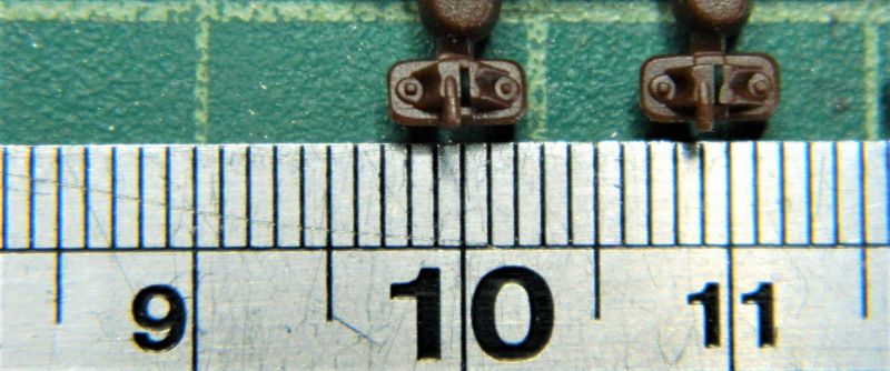
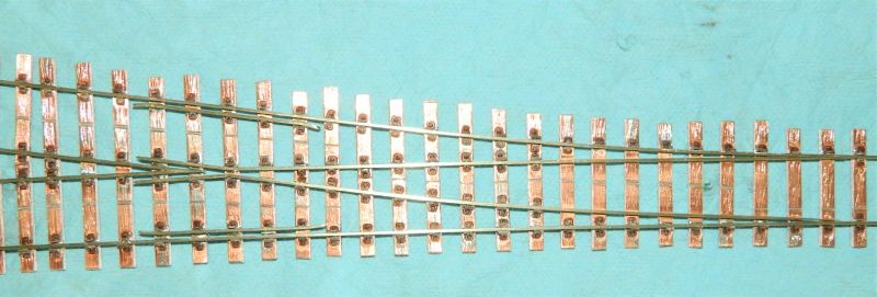
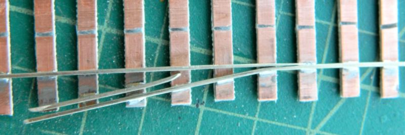
Having found some C+L Finescale GWR 2 bolt chairs I thought it would be interesting to see what it looks like with a bit of decoration. Excess solder was cleaned up using solder braid (copper braid impregnated with flux), the sleepers scribed to give a representation of wood, and the chairs cut in half and the height reduced. Fiddly, these things are around 5mm long. Glued in place using CA. I have yet to add the chairs inside the point ends. I will do that after I have soldered the tie bar in place. Insulating gaps were made in the copper clad with a triangular needle file. All that remains is the wiring and cutting some insulation joints in the rail. Keen-eyed will note the absence of a joint twixt closure rails and point rails. Not necessary with code 75 rail, and it makes the wiring simpler.As an experiment the final 2 sleepers on the main track were glued on using CA (compare photo 1 and 4).
Making, trimming and putting on all these half bits of chairs took longer than making the turnout. Not sure whether I will do this on the remaining 6 points, I have some ideas just using styrene bits (or possibly brass) to give a representation of a chair holding the rails in place. Each turnout needs ~100 chairs allowing for wastage and bits flying on cutting never to be seen again. I have 600 C+L GWR 2-bolt ones left….
Two down, 5 more to do. Plus of course those 2 wagon turntables.
Nigel
Soldered-up turnout (almost complete)
No, it's not poor soldering technique, it's that very slight curve.

C+L GWR 2-bolt chairs. When used as intended the rail is canted at 5% (1:20) to the inside. JLTRT.
"Chaired" turnout.
©Nigel C. Phillips
Posted

Full Member
what is a "matchstick" autotrailer? I've not come across the term before.
Colin
Posted
Full Member
The first autocoach (technically a trailer, #1, Diagram A) had vertical wood planking on the lower half of the body (and bowed ends).There were also other early diagrams with planking but with bowed ends. converted from steam rail motors. Two wooden ex-steam rail motors had flat ends (105 and 106, Diagram A6). From a distance it looks as if the bodies are made of matchsticks. (Matchboarded is the correct term). Very similar to early American Pullmans. I read somewhere that the planks were about 3 inches wide but were actually 6 inches with a groove.
Basically 3 different bodies - matchboarded, wood paneled and metal. Plus those built as autocoaches or trailers from steam railmotors. these have irregular window spacing. Two different types - 70 foot long suburban and 59 foot long branchline. Add to that coach conversions of various types over the years (the Clifton Downs for example) and it makes a rich field that unfortunately is very undermodeled. Many early ones survived until the 1950's.
Matchboarded ones were if the 59 foot long variety, very useful for small layouts with restricted trackwork and short platforms..
I use "Great Western Auto Teailers. Part One. Pre-Grouping Vehicles" (John Lewis, Wild Swan Publications, 1991, ISBN 0 906867 99-1) and "Great Western Coaches (1903-1948" (J.H. Russell, OPC, 1973, USBN 0 902888 04 8) as reference.
Nigel
[Edited from the earlier post].
©Nigel C. Phillips
Posted

Full Member
I've been out of things for a while, so have missed much on the forum, but am in catch up mode and it's good to see your progress on the stock which is now well advanced, including the turnouts as well. The autocoach is looking very much the part now, with good panelling and underframe. Those existing much modified seats look very much like the Ratio product, particularly the back to back units at right angle to the sides, although someone has been very unkind with the others and as you say, far too much space in the longitudinal aisle.
Have you completely abandoned your desire for a matchwood version? They are so rarely modelled.
The potential move sounds interesting and could be particularly beneficial to enhanced layout parameters. I hope it goes as you both wish, so bon courage mon ami.
Best,
Bill
At 6'4'', Bill is a tall chap, then again, when horizontal he is rather long and people often used to trip over him! . . . and so a nickname was born :)
Posted
Full Member
Welcome back. Yes, probably much modified Ratio seats. Nothing like the prototype, which had small legs. I'm leaning towards scratch building using brass or styrene. Or even wood.
Matchstick/matchboard autocoach/trailer. I have been exploring the choices. 1. Bash a current RRR Collett model. The issue here is that the windows are all wrong for an ex-SRM. 2. Scratch build using styrene and or wood. 3. 2D etch in brass or N/S. 4. 2D cut using styrene or acrylic or even wood (my preference here is a laser cut as it will etch the boards, rules out styrene though). 5. Shapeways ($$$). 6. Coopercaft (if they ever get their act together). I bought the BSL autocoach with the intention of just using the buffers. Instead I have a panel autocoach/trailer.
The big issue is the buffers. Two choices here. An old RTR autocoach or wait for the only supplier I have found to restart his business, which is currently closed for the duration. Probably 50:50 that it never restarts. RTR means paying for exorbitant shipping unless one comes up at Hattons. The prototypes ran with a variety of bogies. "American" ones will be fine.
Most of the artwork has been done, and the etching service will take my vector file. That said, scratch building in styrene has its attraction, namely cost. I came across some matchboard styrene sheet in the spares that I had used to build some Pullman passenger cars. Not too far out of scale.
Nigel
©Nigel C. Phillips
Posted
Full Member
I'm glad to know it is still on your radar.
Bill
At 6'4'', Bill is a tall chap, then again, when horizontal he is rather long and people often used to trip over him! . . . and so a nickname was born :)
Posted
Full Member

I know Ron Solly used to build his own and I'd often thought about having a bash but thinking about it was as far as I ever got.
Those chairs look strange - are they supposed to be used as one would have used real chairs i.e. slotted onto the rail and fixed to timber sleepers (ties) ? I thought one could buy half chairs for cosmetic use on hand built track ……….. :roll:
'Petermac
Posted
Full Member
Well, you can sleep peacefully and stop worrying about frog numbers with the small, medium and large radii points - they are all the same. Peco use a #4.76 frog (12° angle). Peco get around this simply by using longer closure rails. That's why there is such a big difference in the length of the points with increasing radii.
Half-chairs. Yes, decidedly odd. I thought Exactoscale did them, but they are not showing on the C+L Finescale site. Same goes for DCCConcepts and Scaleway. The plastic chairs I used are meant to side into the rail (PITA, as they are handed to give the correct cant), then glued to wood or C+L plastic sleepers using MEK (nothing else works).
The issue is that the rail is flat on the sleeper. Fine for FB rail, not so for BH. With a chair it is slightly elevated off the sleeper. which is why I had to reduce the height. The GWR actually used a fair amount of FB rail in the 19th century, but not at Watlington as far as i can determine. The EM Gauge Society get around this by using wooden sleepers with rivet heads where the rail goes and to which they are soldered. These are rather like hen's teeth to get. They have recently moved into the points game by coming up with a RTR #6 B set of points (Peco make them), but using them only covers a 1/7th of what I need. I did investigate a few years ago whether it was possible to get the gap just with solder. It is, but very fiddly. Methinks a much simpler representation (as on the Scaleway flexi track I will be using) is all that is required. I'm trying to keep clear of brass castings as well - they will push one set of points into the £100 each category.
The alternative is to only use a few copper-clads, the rest being wood or plastic. I'll stick with stability that all copper-clad gives and use a bit of judicious representation plus ballast Luckily those half chairs will simply snap off, which is a job for tomorrow as I'm not happy with them either. Nothing ventured, nothing gained. It'll look OK from 3 feet. I suppose I could grind down the copper clad….
Nigel
©Nigel C. Phillips
Posted
Full Member
That's very interesting, something I'd never spotted as I've some large radii Peco points (insulfrogs) on W-H and was always impressed how well my 0-6-0s traversed them relative to double curved points. Any compromise in operation is not noticeable to my eye.Hi Peter,
Well, you can sleep peacefully and stop worrying about frog numbers with the small, medium and large radii points - they are all the same. Peco use a #4.76 frog (12° angle). Peco get around this simply by using longer closure rails. That's why there is such a big difference in the length of the points with increasing radii.
Colin
 Last edit: by Colin W
Posted
Full Member
It's a bullet-proof design. Keeps cost down as well having a frog standard across the range. Big issue of course is if you want a point that is not covered by the 3 radii.Plus I believe the exit is also the same.Been some time since i looked at this (ever since i decided to make my own). I always find it interesting that Peco in it's code 83 HO range has had to come up with frog designs with different frogs that match American manufacturers.
is the same
Nigel
©Nigel C. Phillips
Posted
Full Member
Rain stops play! Well, near enough, I am almost at the end of the copper clad, and running low on code 75 B/H rail unless I cannibalize some of the SMP flexitrack/kits. Copper clad comes from the US, so long as the business is not in lock-down I should be OK. One man business, mail order only, so fingers crossed.
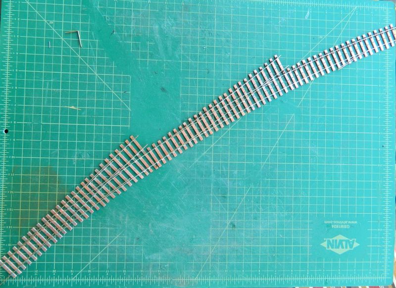
The attached photograph shows the entrance to the yard (branch line lower LHS), minus the turnout for the spare siding and goods shed siding that goes on the second turnout (top RHS).. I even managed to get a working catch point (single rail) on the coal yard siding. I may rework this as I am not that happy with the angle. Wagons derail OK, but they do not follow the rail. Not sure I want to try and put the other 2 in the middle of the turnouts (essentially in the closure rails). I'll probably put them on the sidings.I have a spare turnout, so I will see what it looks like if I cut a section out and have a catch point in the middle of the closure rail. The size of the cutting mat is 24" x 18" (61 x 15.5 cm), gives an idea of how big this sub-assembly is (almost 30" long, 76 cm). I may stretch it a bit by extending the curve on the first turnout as I have decided to increase the width of the baseboards by 6".
The next sub-assembly is the run-around at the station and the engine shed/carriage shed sidings.This needs 4 #8 turnouts.
Nigel
P.S. That little right angle piece of rail in the TLH corner is a quick look at how I am going to do the rails for the two wagon turntables.
©Nigel C. Phillips
Posted
Full Member
'Petermac
1 guest and 0 members have just viewed this.