A Final Curtain Call for Westown-Heathfield
Posted

Site staff
GWR OO Gauge - 1930's rural Somerset - Winter 1937
Thanks Colin :thumbsEd

Posted

Full Member
After my 2.5 month wait for the Peckett, last Friday I was amazed to receive a UK package in just 2.5 weeks, full of DCC goodies for it and much more.
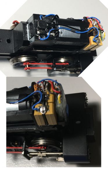
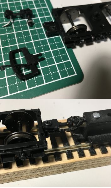
But first to my little birthday present, the last part of which was the DCC chip and SA to get it going as the gasworks engine on W-H. Hornby have done a remarkable job of fitting in everything including space for DCC in such a tiny loco as these photos show. Note the chassis proper is a mere 65mm long!

However true to form the DCC fittings are set up for a Hornby proprietary 4 pin chip bearing a socket rather than conventional pins. It's not clear in the photo but the blanking "plug" is a socket.
Fortunately this is no matter to me as I need a Stay alive on W-H so won't be using a Hornby chip. The RH photo shows a pre-assembly schematic with one of the smallest ZIMO decoders.
The DCC Chip has a neat bay up front. the chip is sitting in it.
Red lines mark planned cuts
- The Hornby DCC mount comes off, replaced by direct wiring to the chip
- The SACC 16 circuitry is snapped off leaving just the core electrics on top
- The contact pads section will go behind the DCC (green arrow) with as many tantalum caps as I can squeeze in there or where the original socket and blanking plug were sited alongside the motor.
one cap is visible in the SACC pack at left
The remaining wiring changes are not shown but will involve soldering the SA wires direct to the DCC chip, connecting these up to the SACC and this in turn down to the various tantalums.
Busy few hours ahead!
 Last edit: by Colin W
Posted

Full Member
Would it be possible to go into a bit more detail on soldering the SA wires to the decoder? What size bit do you use for instance?…..My attempts have not been very successful so now I get John at Youchoos to do it for me.
I have quite a fancy soldering iron but think I may have the wrong bit….. mind you it could be old age….shaky hands and poor eyesight

I am building up quite a surplus of replaced Lenz chips but I am not sure if there is a ground (-ve) Solder pad on them?
Best wishes
John
Posted

Full Member
I can hardly see them, let alone solder to just a part of them.
Would Sellotape hold ? :cheers
'Petermac
Posted

Full Member
Michael
Posted
Full Member
The iron I bought had a very fine tip but I'm not sure of the quoted size. It's small enough to touch individual tabs on the tiny MX617 but you need steady hands. I'm lucky in that respect but I've noticed in the 6 years I've been back into modelling how much better my steadiness has become, practice makes….better?
My soldering work has improved since I switched from using a wet sponge to the springy brass turnings to always keep the tip clean.
To connect to a terminal I get a little solder on the tip, quickly wipe clean in the brass and lightly touch on the tab. Then I bring a tinned wire up to the tab and heat on the wire just beyond the junction, this provides enough heat on the join area to make a good joint.
The Peckett was the hardest job I've tackled, installing a simple chip is fine but literally there is the barest space to work in for any extras and with a metal chassis and body the risk of shorts is a limitation. Hornby have done a fine job with the design, I'm impressed, but it severely limited the options I had. Avoiding wires getting trapped and pulled off was an issue but in the end my original plan came good as shown here.
There is just 7mm between the motor front and the chip, the tantalum array just fits snugly there leaving with a small cavity for the various wires. The SACC electronics board is just 2.5mm thick and then only at the biggest component. Siting this item in the centre the whole 9mm * 8mm fits on top behind the motor held in place with blacktac. The loco is now a very fine runner over my points, even the double curves with their long frogs if it has a bit of speed up. After that little airing, it will spend all its time busy with coal wagons heading for the gasworks (off scene) and I'm sure it'll be a hit with the youngsters when they can come over next.
Posted
Full Member
Sorry, I don't know Lenz chips but ZIMO are very helpful by providing a chip diagram with all the accessible tabs and wires clearly labelled. I've even been able to identify and reuse my Bachmann 36-358 (which is made by ZIMO) thanks to their helpful literature.
You could check the Lenz site for a manual to see if that helps.
Colin
Posted
Full Member
I will do some more research with Lenz
Cheers
John
Posted
Full Member
I too gave up on the damp sponge some time ago - it simply didn't seem to make sense - get your iron hot then dab it on a cold wet sponge - probably losing 10 or 15 degrees of valuable heat in the process !! The pan scourer type are much better although they do eventually fill up with solder debris …………..
The "steady hands" would defeat me I think. I usually set out with all good intention but then wonder why I'm attempting to solder whilst my hand insists I should be playing a guitar …………………and isn't the wire thin !!!!
I will continue to practice and see what transpires …………….I have a few non-DCC (split chassis) locos I'd like to have a go at so keep looking at "how to" articles and think it looks so simple - then I chicken out ………….
'Petermac
Posted

Full Member
Nigel
©Nigel C. Phillips
Posted
Full Member
Another item in last Friday's Postman's big delivery was Sound for 6424, my other Auto train loco. Installation was similar to that for 5775 (last June) but with the benefit of experience, a better job was done with the Sound chip and speaker forward in the boiler and the Stay Alive circuitry / firebox LED in the cab / firebox. Plenty of room left for crew.
By removing the entire cab structure the whole job was much easier, worth noting and a useful tip from YouChoos. Maybe the 57xx structure is sufficiently different to exclude that option?
This shows the install with the loco pulled apart after completion
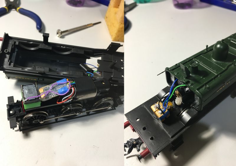
The SACC circuitry sits between the blue and green LED wires in the top of the firebox. The orange LED is strongly attenuated and if I can find the CV, I'll tweak the flicker rate down from the default. It's operated along with Coal shovelling on F3. A video should be up in a day or so.
The existing 6 Pin Bachmann Chip in 6424, a ZIMO MX622 in disguise will be migrated over to the WC&PR Terrier (how appropriate, another hand-me-down) where it will give me the ability to add some decent SA capacity to that loco.
Posted
Full Member
You haven't by any chance got a split chassis Bachmann J72 or V1 to do have you ………………….? You could post it on here just in case any members might be interested in finding out how to do them ………………… :roll: :roll: :cool wink
'Petermac
Posted
Full Member
Sorry, I can't help you with the split chassis issue. With the admiration I have for my Bachmann locos, I've often thought about buying a split chassis model of theirs but TBH W-H is "house full!" so I've never looked into what would be involved. Hence my recent diversions to the gasworks loco and my WC&PR virtual railway project.
Posted
Full Member
Some things to watch out for.
1. The motor terminals have to be isolated from the chassis halves. Heat shrink over the wired terminals and a thin coat of 2 part epoxy on the body solves that.
2. The insulating bushings that hold the chassis halves together often are perished. Replace anyway with new.
3. The white spacers at the bottom tend to go walkabout, guard safely. Dab of grease keeps them in place when reassembing.
4. Where the screws go into the chassis halves for the DC to decoder wiring to a large extent depends on how much space there is available, and whether the wiring goes to the tender. If the body shell is a tight fit the screws often need counter sinking and channels cut.
5. Always check the split axles. Splits in old models are common, newer replacements are often changed and not compatible with the wheels. If they are split then think hard about going ahead with the conversion. I binned 3 Bachmann Manors and a K3 because of split axles and no replacements.
Nigel
P.S. I usually drill and tap, but drilling with self tappers also works. Do not be tempted with soldering to the chassis, it needs special aluminum flux and solder.
©Nigel C. Phillips
Posted
Full Member
Both locos I have in mind run perfectly on DC so I could either sell them on or risk sacrificing them as a learning function ……………..
'Petermac
Posted
Full Member
Hi PeterThanks Nigel. I'm not sure I'm competent enough to do one yet - I did tackle one an age ago with John Dew holding my hand but ended up virtually replacing the whole of the works - cheaper to buy a new loco.
Both locos I have in mind run perfectly on DC so I could either sell them on or risk sacrificing them as a learning function ……………..
That was a very good summary of the issues from NigeI
For a first attempt we didnt choose the easiest of subjects……. if I recall it was a 2-6-2 V3(?) with complicated valve gear?
The J72 is an 0-6-0 tank and much more straightforward……… in many ways the ideal starter kit.
If you are quite satisfied it is a sound runner on DC its probably worth a go.
Happy to help again……… although after my recent exploits I would quite understand if you prefer that I dont get involved!
 ……..
……..Regardless we should probably start another thread! No problem for an all-powerful Mod
Best wishes
John
Posted
Full Member
'Petermac
Posted
Full Member
Nigel
©Nigel C. Phillips
Posted
Full Member
A brief period of respite allowed the girls to stay over during the school Hols but this has been brought to an abrupt stop. I hear it's made the news elsewhere so won't dwell on the details other than to note the situation now is more severe than in the first "peak". 6 more weeks of home stay with exceptions very limited.
We did have two fun days here with C&S and they helped me enthusiastically to do rolling measurements on all my wagons. We set up a ramp, ~4% incline and measured the time for wagons to roll down. One was starter, the other saying "stop" (mostly!) and me on the stopwatch. Good "science" required us to do multiple runs and much interest was shown in why the results varied widely, the worst not even getting away.
Now that they're back home for more home schooling I've turned to fixing up the problem wagons. Two had brass bearings added, not the easiest job on an assembled vehicle. Two very old Airfix were so corroded that simply burnishing the rust off the metal axle points and cleaning the holes worked a treat.
The surprising discovery for me was that the best brand in my collection was without a doubt Hornby. They all whizzed down even gentler gradients than my test slope. Now there's a turn up!
Last edit: by Colin W
Posted
Full Member
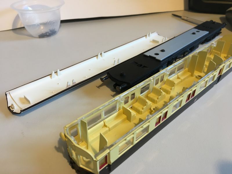
I've done lot in recent times working on locos for Heathfield's passenger services improving my Class 48xx and 64xx Tank Engines which were fitted for Autocar operations. Now the time has come for more focus on the Autocoach itself.
As an aside, I've taken advantage of the new locker service provided by Hattons which has allowed me to buy items, then have them held until it suits me to ship them. This has proved very handy; pre-owned items which would not be worth buying / shipping as a single item, pre-orders etc. etc. In this way I've picked up a range of goodies, some at great prices and then consolidated them and splashed out for the security of Courier delivery to Oz and now they're here.
It'll be no surprise that one such item was an Autrocoach, no 190, a neat companion to my no 191 and allowing me to run the holy grail of Autocar configurations, two car services. Before putting them to work I did some cosmetic work as the bland GWR yellow interior screams out of the large windows - change me!
The next photo (l) shows the interior after painting to some GWR colours of the era with an attempt at Teak panelling. Fortunately it's not that visible from outside (2 ft rule) other than giving an impression of the contents. A few seated passengers are more visible once the roof's back on, they're modest types but paint up nicely to my mind.
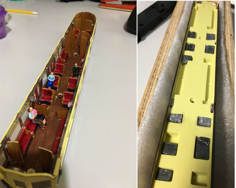
On the right the various lead offcuts (45g) inserted in the convenient notches of the seat moldings. I've not had an easier vehicle to add weights to, bringing it up to 170g gross.
Finally, the couplings.
Hornby - I have a "troubled relationship" with these guys, having bought more dodgy locos of theirs than anyone should ever get and then some brilliant items when they get things right. On the autocoach, this next photo shows one classic example. This is a very old molding but in its latest versions (since ~2017) has had a substantial makeover on the exterior and despite the omissions looks good under the 2 foot rule. By why stick with couplings like the giant "D", from the Dark Ages. Surely the bogie could have been reworked to provide a NEM pocket, or a suitable bogie from some similar coach substituted with minor mods?
It was not a big job to prise off the old and add Kadee Gearbox #31 which works without buffers locking.
1 guest and 0 members have just viewed this.