A Final Curtain Call for Westown-Heathfield
Posted

Full Member
GWR OO Gauge - 1930's rural Somerset - Winter 1937
I love it when someone finds a use for an item that would otherwise be thrown away, and that is one I will be adding to my list of things to look out for. Brilliant!Michael

Posted

Full Member
Hi Peter,That's a brilliant idea Colin. :thumbs I wonder - do your walls smell ?
What is even better about this method is that I get to eat 2 whole boxes of Camembert "Rustique" for every wall.
I'm going to model the whole of the Yorkshire Dales……. :Happy
Joking aside, those header stones look excellent. Are they really just Das clay ?
I learnt from a true master of working with DAS who has modeled a fair chunk of fell walls on a patch of the S&C line and whose most recent model is the Arten Gill Viaduct in full DAS, many thousands of individual stones here Arten Gill in DAS
Stone Wall Jig
Back to my more modest efforts, I built a jig, a variant of Jeff's version to cast strips of DAS in required sizes. These pics show the basic structure made from a lightly textured melamine covered chipboard offcut, the sort used for durable shelving. Two strips of 3mm HPVC (ex Venetian Blind strips) are used for the sides of the jig #, convenient as they cut easily and can be planed true. One was fixed the other can be positioned for different widths of clay strip.
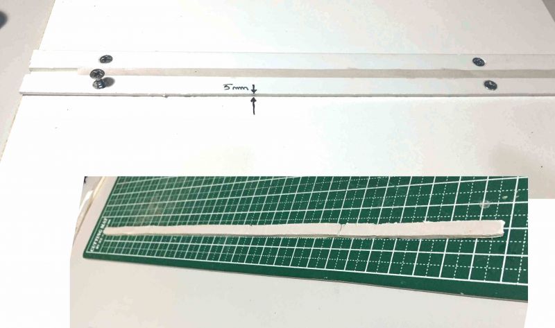
The DAS is rolled out to a long sausage then pressed into the jig and smoothed flat with a wet finger. It can be rolled flat with something like an AA battery as long as it's kept slightly wet. After a very brief wait, one side of the jig is removed and the thin strip carefully slid out, a painter's spatula is good for this.

Here I was making 5mm and 7mm width stones all of 3mm thickness for a bridge fascia. Production is relatively quick.The strips are left until almost dry as they are easier to cut up that way than when fully set.
For dry stone wall topping I made strips of 3mm, 2.5mm and 2mm thickness, these being the width of stones seen side on. The strip needs to be a tad wider than your wall width. By cutting across the width of the strip on a slight angle the stones will then sit slightly lopsided. Random tangential cuts for the tops produce the "look" of the final wall.
I create a whole batch then pick and choose from different widths and cuts at random.
# I've not made any 2mm and 2.5mm thick stones on this jig yet. I'm considering using a 0.5mm / 1mm PS sheet strip as an insert, perhaps with little side lugs to stop it pulling out when I remove the strip.
Posted

Full Member
Staying on the thread Kevin.
Posted
Full Member
Headmaster posted this on Monday in response to the same question and so has already answered you.:Hi Colin………….I have an empty space in the middle of my Inglenook which may be suitable for a coal merchant, I have been reading through your thread again and would like to make some cobblestones , with DAS clay would these stick to plywood with PVA glue? Best wishes Kevin
Passed Driver wrote:
"Hi Kevin, I have posted a reply in your thread after Bill's wise words "Hi Michael. I have been considering the middle ground on my Inglenook, because DAS clay is unlikely to adhere to the plywood baseboard, unless of course there is a medium, glue or whatever , with my cackhandedness I don’t know if the cobblestone sheets would last long and then there the joins to cover up . Have you got any reasonable suggestions that would work with a coal yard? Apart from that keep up the good work. Best wishes Kevin
I suggest you write yourself a little note with date / time /where you post a question so you can follow up responses and avoid going thru the same cycle multiple times :cool:.
Posted
Full Member
A lot of my early kit builds were completed before I came to posting here and even my reworked cottages already had been dressed up in new Scalescenes stone and roofing. Back then the space opposite Heathfield station was a gaping hole in search of a building and I had no clues about constructing something to suit.
When compared to the amazing scratch buildings turning up all over the place on here, these early efforts were modest. But then I thought they might interest folk otherwise put off scratch building by seeing a massive Hotels, Aussie Victorian Railway Station or Elizabethan streetscapes knocked together with apparent disarming ease!
Building a few Metcalfe Kits is a good starting point because they impose a discipline about process, alignment and care. The instructions are comprehensive and everything you need (except flashing!) is supplied.
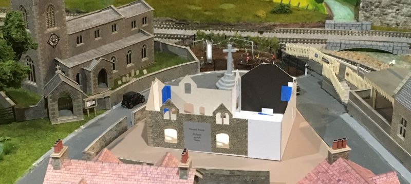
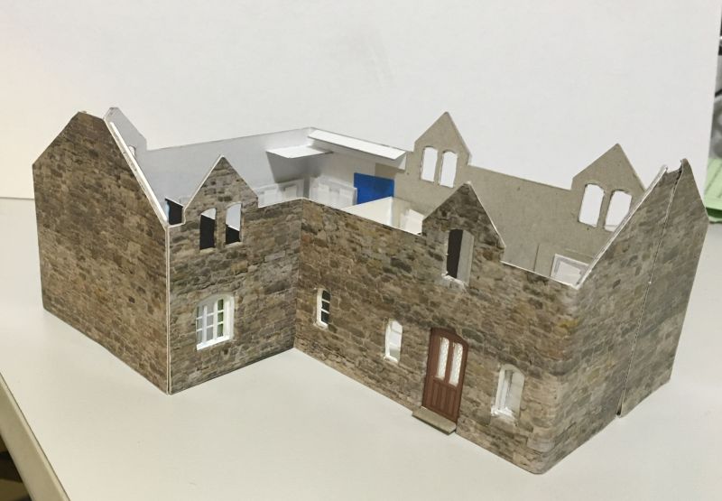
I decided the house I needed between Church and station might well have been a Vicarage built in times when these could be substantial properties. As it happened I got some useful help as one of my Metcalfe cottage kits was mis-registered on one sheet and a replacement was mailed out to me. This gave me a handy set of wall structures to use as a partial core for the building, a free experiment!
This was the empty space

The shape, held with masking tape during my trials.

and tested on its own removable "island" in situ
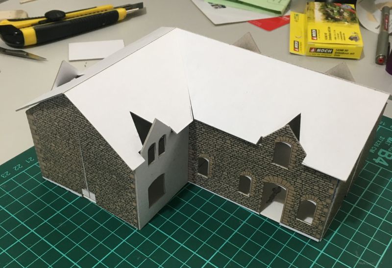
Looking good, I moved onto the roofing. The empty Metcalfe roofing sheet was a perfect template as a starting point for size and dormer positioning.
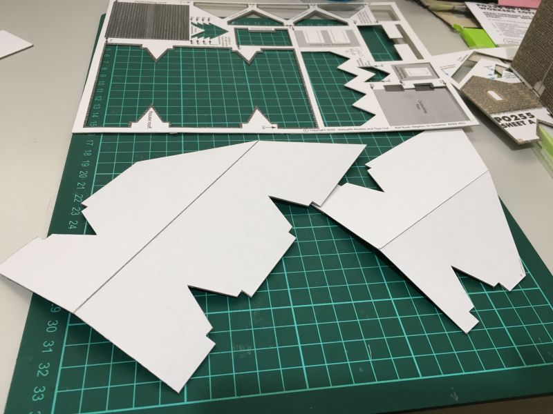
The angled join was the tricky part but came good after a little work.
The misregistered / otherwise useless printed sheet can be seen here in its new role.
Part II will cover the walling, tiling and other finishing items.
 Last edit: by Colin W
Posted
Full Member
Staying on the thread Kevin.
Posted
Full Member
[yt]YEY8HnuA6NQ[/yt]
While W-H is a tiny layout I do have one luxury which I'll miss if/when I move on to something new. There's just enough running room to capture a King either pulling away from Westown or opening the throttle for a run through open country with a good complement of coaches. Here 4 Collett Bow ended Corridor and 2 Clerestory stock
One of life's little pleasures
Posted
Full Member
From Sept 2019
[yt]tTdkE1CuBdE[/yt]
From Oct 2019.
[yt]RjnUBr6LA2I[/yt]
and last May
[yt]2nNujIruqYk[/yt]
# Fortunately electrons are cheap and the links tiny so not placing a huge drain on the Club server storage :twisted:
Last edit: by spurno
Posted

Full Member
Which sound chips did you use ? The firebox flicker looks effective there - I'd always considered it a bit "OTT" but now I'm not so sure…………
'Petermac
Posted
Full Member
Peter,Those are excellent clips Colin - I enjoyed watching them. :thumbs
Which sound chips did you use ? The firebox flicker looks effective there - I'd always considered it a bit "OTT" but now I'm not so sure…………
Thanks. With just one exception (the Collett Goods), all my sound chips are ZIMO from YouChoos. I was given a recommendation to use them and it has proven to be excellent advice. I've always received excellent service. AFAIK their Steam sound packages all have provision to add a firebox flicker. Simply installed by wiring LED to the green chip wire and relevant neutral and then activated by using the F3 control which is linked to turn Coal Shovelling on/off as well.
I've read of several new locos being offered with the glow feature so that must mean the LED is pre-installed. I had to install my own, fortunately YouChoos' online documentation makes this straightforward.
Colin
Last edit: by Colin W
Posted
Full Member
Staying on the thread Kevin.
Posted
Full Member

That is actually very convincing with the flickering light! Lovely videos mate.
Cheers,John.B.:thumbs
Posted
Full Member
Ketley Hall 4935 from Hornby's Railroad range has an amazing amount of detail and quality given its place their "budget" range. One very experienced GWR modeller has used it as a good inexpensive kicking off point for highly detailed modifications - high praise.
I've been very happy with the loco, a fine runner, workhorse on W-H but I've turned my attention to adding a crew for some new shots and videos. On looking I found it lacks one crucial detail, the junction plate between cab and tender and today I set about adding one. Fortunately it's has a pedigree, it must come from the same mold used for modern Halls in the Premium range and so it has two handy holes in the cab floor ready for the plate! (will marvels ever cease
)All needed was a simply knocked together sheet of 0.5mm soft PS sheet and two flexible brackets. The fireman appears happy with the result!
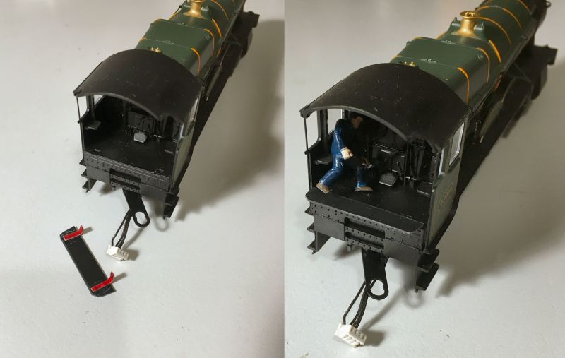
As for the driver he's currently having some "plastic" surgery! Using items from Dapol's railway workers sets (C002) for my crews, the various bits sometimes need a few mods to meet purpose. Today my driver had his right arm repositioned by 180 degrees - reattached with PS / limonene putty.
Posted

Site staff
Cheers
Matt
Wasnie me, a big boy did it and ran away
"Why did you volunteer ? I didn't Sir, the other three stepped backwards"
"Why did you volunteer ? I didn't Sir, the other three stepped backwards"
Posted
Full Member
Oh dear, rumbled again, I'll get on with it sir.Playing catchup again Colin, liking the Vicorage scratchbuild, are you still working on Part II ? I'm interested to see how this turns out ! :thumbs
Cheers
Matt
Colin
Posted
Full Member
With the basic structure in place, the next step was to add internal lighting, not a job to remember to do later!

Next the printed Scalescenes "TX47_OO Coursed Rubble" which looks a lot better than it sounds. I always get mine printed on heavy (200gsm) paper at an Office suppliers for the quality and durability of the print surface. For best appearance, I try for minimum joins located at least viewed corners, this gives other corners a better look.
The walls were already thick from the kit components before adding this new extra sheet of heavy paper so it was relatively easy to get an indented effect in the window and door frames. Spares from my various Metcalfe kits gave me enough windows for downstairs. Upstairs were cobbled together from thin PS strip.
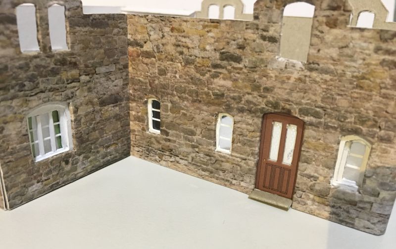
Finally the roofing was much as described on the Cow Shed, Scalescenes layered slate tile strips and all printed surfaces painted with a clear Matt acrylic sealant.
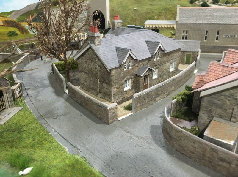
Here is the almost finished Vicarage winter 2021, now all it needs is some flashing around Chimneys and roof channels
Last edit: by Colin W
Posted
Full Member
Having fixed up the footplate gap and the crew I thought I might as well take the advantage of having cab access to complete the detail of the cab moldings. My reference source in absence of a Hall Cab photo are these from Steam Swindon taken in 2016.


referring back to my own Hornby King model (6011) I can see the detailing completed as intended on non-Railroad model releases. A useful guide but I noted one artifact which must be purely in the mind of the model designer as it's not on the original!
The Hall cab face is very similar so it was straightforward to complete the painting of the main features. Once done it's interesting how the appearance is improved.
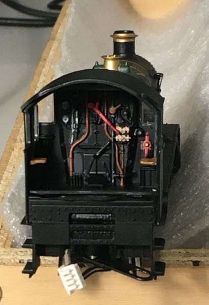
In all, two very easy upgrades to bring my budget Hall up to full specs :cool:
Last edit: by Colin W
Posted

Full Member
Hi Colin,Heathfield Vicarage - Part 2
With the basic structure in place, the next step was to add internal lighting, not a job to remember to do later!
Next the printed Scalescenes "TX47_OO Coursed Rubble" which looks a lot better than it sounds. I always get mine printed on heavy (200gsm) paper at an Office suppliers for the quality and durability of the print surface. For best appearance, I try for minimum joins located at least viewed corners, this gives other corners a better look.
The walls were already thick from the kit components before adding this new extra sheet of heavy paper so it was relatively easy to get an indented effect in the window and door frames. Spares from my various Metcalfe kits gave me enough windows for downstairs. Upstairs were cobbled together from thin PS strip.
Finally the roofing was much as described on the Cow Shed, Scalescenes layered slate tile strips and all printed surfaces painted with a clear Matt acrylic sealant.
Here is the almost finished Vicarage winter 2021, now all it needs is some flashing around Chimneys and roof channels
I can see you use a LED diode and a resistor for your lighting. How 'big' is the resistor and what is the voltage of the lighting system?
Cheers,
Claus
www.flickr.com/photos/ellef/
Claus
www.flickr.com/photos/ellef/
Posted
Full Member
The PS is 12VDC regulated, an old charger of some description. I match the current regulating resistor to the number/ type of LEDs in the circuit as this varies depending on the building being lit.[user=2170]Colin W[/user] wrote:Hi Colin,
I can see you use a LED diode and a resistor for your lighting. How 'big' is the resistor and what is the voltage of the lighting system?
The resistor depends on the LED type as each has its own voltage drop VL
I aim to have a low current to produce dimly lit LEDs which are best suited inside buildings. From trial and error with Warm White 3mm LEDs (VL = 3.4V) I've found around 12-14mA to be best.
A worked example for 3 LEDs -
Voltage drop across 3 * LED in series = 3*VL = 10.2V
Required Voltage drop across resistor in series = 12- 10.2 = 1.8V
Resistor to control circuit current at 12mA is derived from R=V/I = 1.8/0.012 = 150 Ohm
If I need more LEDs than this in one setting I add additional sets in parallel, each with their regulating resistor.
Posted
Full Member
Thank you, Colin. I like to see my science/physics teaching at work :Happy[user=2172]Claus Ellef[/user] wrote:The PS is 12VDC regulated, an old charger of some description. I match the current regulating resistor to the number/ type of LEDs in the circuit as this varies depending on the building being lit.[user=2170]Colin W[/user] wrote:Hi Colin,
I can see you use a LED diode and a resistor for your lighting. How 'big' is the resistor and what is the voltage of the lighting system?
The resistor depends on the LED type as each has its own voltage drop VL
I aim to have a low current to produce dimly lit LEDs which are best suited inside buildings. From trial and error with Warm White 3mm LEDs (VL = 3.4V) I've found around 12-14mA to be best.
A worked example for 3 LEDs -
Voltage drop across 3 * LED in series = 3*VL = 10.2V
Required Voltage drop across resistor in series = 12- 10.2 = 1.8V
Resistor to control circuit current at 12mA is derived from R=V/I = 1.8/0.012 = 150 Ohm
If I need more LEDs than this in one setting I add additional sets in parallel, each with their regulating resistor.
Cheers,
Claus
www.flickr.com/photos/ellef/
Claus
www.flickr.com/photos/ellef/
1 guest and 0 members have just viewed this.