00 Gauge - The Heatherburn Garden Railway.

Post

Posted
Rating:
#39719
Guest user
Dave you said in your post earlier

I have decided to keep things simple  :mutley:mutley:mutley

i have looked through your thread from start to finish and i have also trawled the online dictionaries looking up the word SIMPLE. your layout and the word simple should not be mentioned in the same sentence. OHLE, working signals, relays and automated start\stop …… NONE OF THIS IS SIMPLE……

so why should your panel be different?


good luck with the job
Back to the top

Post

Posted
Rating:
#39722
Avatar
Full Member
Another cracking video,Dave……as usual! keeping everything crossed for the result of your  job interview.

Cheers,John.B.
Online now: No Back to the top

Post

Posted
Rating:
#39858
Guest user
Yesterday I decided to make a start on the control panel. Heres some pics….


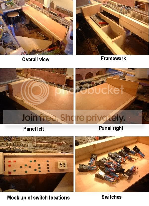
In the first pic you can just make out a diaganal piece of wood. This is one of the steps that I have also fitted making access into the control area easer. It also doubles up as a seat! The panel is being made from left over laminate flooring that will hopefully match the rest of the room. The switches are 4 pole changeover push button with some latching and some not. They can be lit using the 2 24v bulbs located under the switch cap. Some of the buttons have split caps the pics dont realy show them up very well. These will be used for point switching with the green/blue sides showing direction. I have come up with a way of wiring the points using a relay conected to the point switch. If I feed the wire from the switch to the relay common then use the relay contacts to switch between the point motor coils I can get away with using one push button for each point or crossover. So all the points on the station approch will be controlled by 7 push buttons! I also have some flip over covers that fit over the switches. I will be fitting one over the switch controling the return chord to the garden. I will be wiring this via the switches for the 2 crossovers so that all the switches are interlocked. So when the crossovers are set to access the inside loop the switch for the chord will become active. Also once this switch is pressed I need to disable the crossover switches. This will give me the two operating modes for the railway with the simple push of a couple of buttons. Just have to figure the wiring out now!! :thud:lol: ;-)
Back to the top

Post

Posted
Rating:
#39865
Sol
Guest user
And I am in the process of reducing my wiring for point control!
Back to the top

Post

Posted
Rating:
#39989
Guest user
Morning guys just got time to post a couple of pics of the control panel before I have to set of for my interview in thirsk.


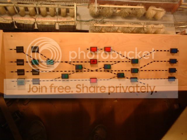
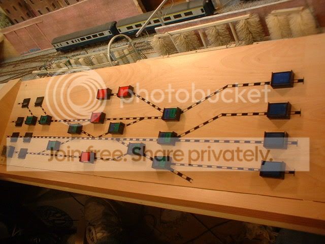
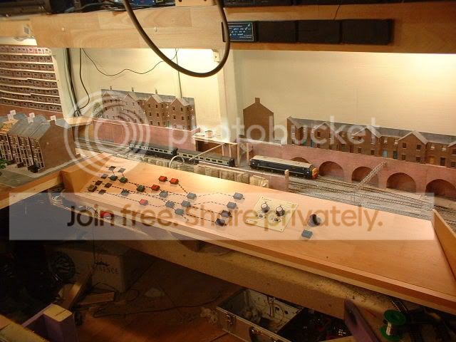
The blue ones control the isolating sections in the station, the red control the isolating sections outside the station, the green/blue switch the points and crossovers while the green switch the points least used for the parcels and branch. The rocker switches are 'service' switches for the track supplys while the one at the bottom far left with the cover over controls the return line back to the garden. The rotory switch on the right controls all the signals with each signal being given a number. The signal will therefore be simply 'dialed up' and set to green by the push button below. Nice and simple! :lol: ;-)
Back to the top

Post

Posted
Rating:
#39993
Guest user
Thats a very, very nice control board, Maybe oneday i will upgrade mine, but my temporay control board is good.
Back to the top

Post

Posted
Rating:
#40044
Guest user
Big changes are happening on the railway today. After some thought I decided that the station aproch is'nt looking right so this afternoon the axe is coming out!! The area in question is the background in the last pic. The row of houses on top of the arches just dosn't look right. They have now been removed along with the arches and will be replaced with a blue brick retaining wall. A new road bridge will cross the railway at this point while the other road bridge across the ends of the platforms will be religned. Pics later now wheres that axe!! :twisted:
Back to the top

Post

Posted
Rating:
#40046
Guest user
The panel looks really nice Dave

Switches from vending machines come in usefull:lol::lol:

Tims axe will be busy this afternnon then the trouble with using the axe in tends to increase your workload more once you start using it as its easy to get carried away and decide to do other things while in the axe wielding mood.

cheers Brian
Back to the top

Post

Posted
Rating:
#40063
Guest user
Thanks Brian. The switches were off an old control panel from a chemical plant! Right just a few pics to give an idea of what im trying to achieve. First is the origanal idea of a bridge joined to the end of the control panel…


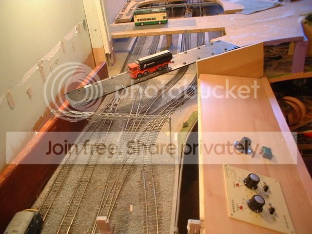
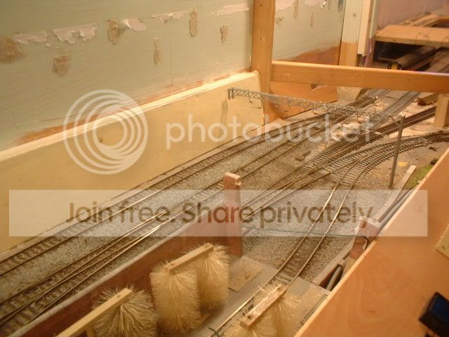
I still carn't make my mind up about having two bridges but the new one will be on the skew matching the bridge further up the line. With the area cleared I decided to sort out the dodgy trackwork leading into platform three……


When the platforms were origanaly built I was using hornby pointwork. This was then changed for peco but the angle was shallower. So as the area is being redevloped I have altered the platform and straightened out the track…


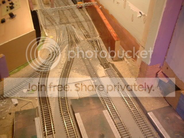
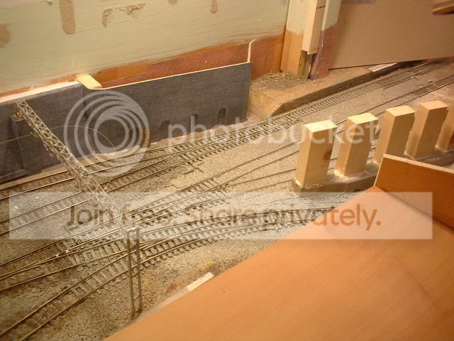
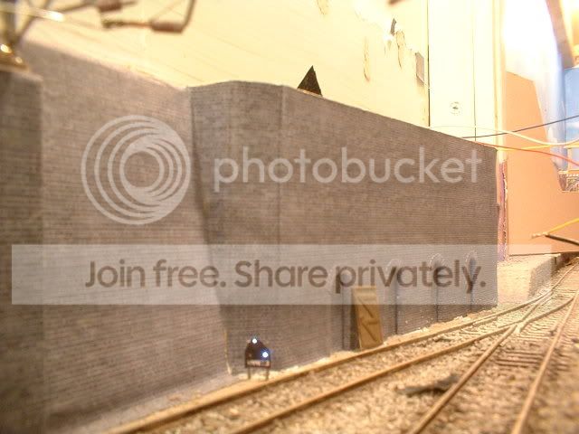
The row of arches has now gone being replaced by a sloping retaining wall….


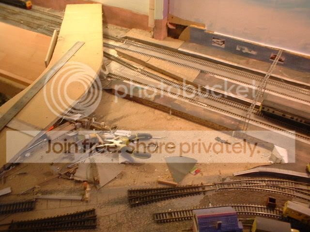
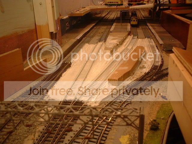
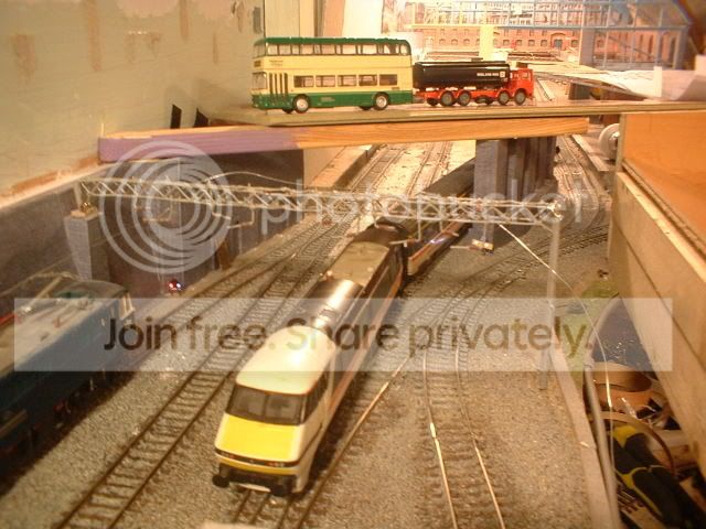
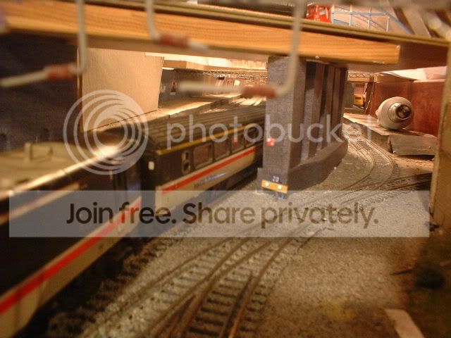
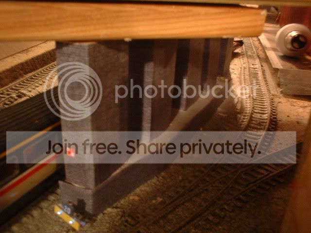
The final position for the bridge has been moved further back with a set of piers between the tracks….


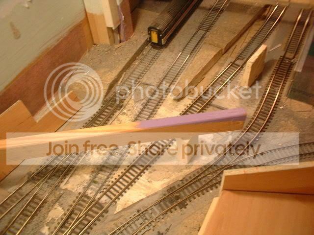
The return line will now be built over possably with a petrol station on top discuising the sharp second radius curves. Finaly heres one of the base for the piers. The white stuff on the track is decorators caulk as I want the track to look like its laid on a slab of concrete….


More later…
Back to the top

Post

Posted
Rating:
#40068
Sol
Guest user
No stopping you Dave when you get a bee in your bonnet! And I thought I was quick to re-act to a thought/decision?
We can all blame a certain person & his AXE!
Back to the top

Post

Posted
Rating:
#40086
Avatar
Full Member
Those block of flats that you built and featured on You tube look fantastic.  I have one question what did you use to make them and do you have a down-loadable file that I could use.


William
Online now: No Back to the top

Post

Posted
Rating:
#40121
Guest user
Hi William the artwork for the flats was done using a program called picture it. This came perloaded with XP when I bought the PC. I started by scanning some brick paper then inserting it into a blank document. The trick is not to alter the size of the pics when importing. I did the same with a window and a door off an old triang station building. This is how I got the artwork for the station building outside. For the flats I used the window and door to get the size and basicly just drew the new doors and windows to fit. The program is very easy to use and I have the artwork on the PC so if you have the same software I can send you the project file if you like. That goes for any one else if they fancy a go. The flats themselves still need the walls adding to the walkways when I can afford some more modeling stuff! ;-)


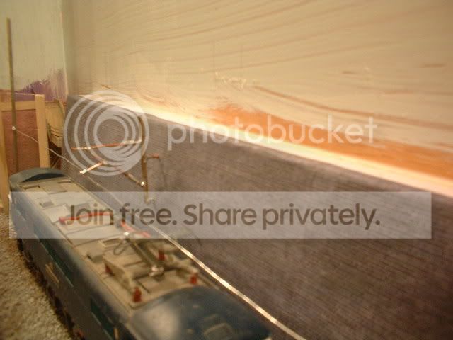
Right. After posting last night I printed off some engineers blue brick for the wall. The basic look im after is birmingham new street without the office block station building! As the wall slopes I had to find a way of refixing the OHLE gantry. A quick look through the books resulted in a piece of softwood cut in a long triangle shape……


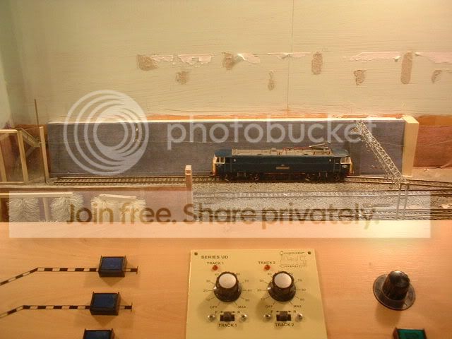
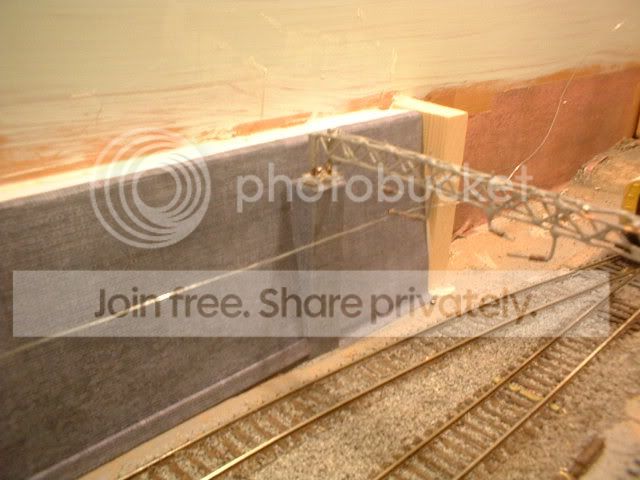
To support the OHLE further along the wall I have bracketed a small mast off the wall to attach the arms to…..


For the wall under the new bridge I had a go at some arched recesses for the track workers. They were a bit of a pain to cut out but should look the business when finished. ;-)
Back to the top

Post

Posted
Rating:
#40222
Guest user
A little progress report on the 'new works'. Yesterday I got the bridge abutment finished complete with refuge's and installed the first working ground signal. The led's for the ground signal are hidden inside the bridge abutment with the fiber optic passing under the wall. As this stuff is clear from normal veiwing distance it carn't be seen and the signal looks amazing when its lit! Heres a couple of pics…


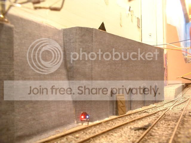
Hopefully the bridge piers will be solid enough tonight so I can add the brickpapers.
Back to the top

Post

Posted
Rating:
#40227
Guest user
plenty to keep you occupied for a few days then Dave, looking good
from where i am.

:doublethumb:lol::lol::lol::cool:
Back to the top

Post

Posted
Rating:
#40350
Guest user
Managed a bit more work on the layout. The bridge centre piers have now been covered with brickpaper and for somthing a bit diffrent I have added a tempory speed restriction sign. The two white lights on this are lit again using fiber optic pipe and will be rigged up to flash. To give an idea of the finished area I have placed some wood over the railway……


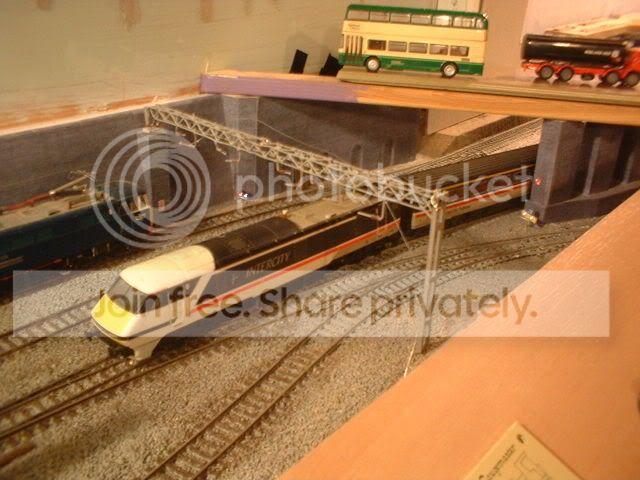
One idea that im seriously thinking of is to build some working theater light indicators for the signals at the end of the platforms. The signals themselves will be on a gantry just under the bridge so I can feed the fiber optics up under the bridge to the led's. I just need to work out what letters to display on the signals. I already have M for the main line, B for the branch, D for the parcels depot? , S for the stableing siding?? Any ideas ???
Back to the top

Post

Posted
Rating:
#40389
Guest user
It would depend on which other routes you wanted it to give.  Normally you would get a number corresponding to the platform number for example.
Back to the top

Post

Posted
Rating:
#40404
Guest user
Chris is there a standard set of letters used for route indicators? Depending on how hard they are to make will determin how many I have at the platform ends! If the signal was located on the lines leading into the station then it would just be numbers 1 - 4 to corispond with the platforms but the ones im building will be going the other way. For the stableing siding off platform 1 I might just use a position light to keep the route indicator simpler however from each platform I have the following routes; Main line, Branch line, Loop round to the TMD (might get away with branch again) and access to the parcels depot. All depends if I can put 35 small holes in the plasticard without it dropping to bits! :roll: Any help apreciated. ;-)
Back to the top

Post

Posted
Rating:
#40416
Guest user
this will be one to watch:shock::shock::shock::shock:

i have seen this done but i cannot remember the layout, an article on the wirrel finescale site show how to buid light signals with route indication. it may help


wirrel finescale
Back to the top

Post

Posted
Rating:
#40473
Guest user
Not really any standard Dave, other than that platforms are usually referred to by number and lines by their letters.

What you had for the lines other than platforms is probably what they would use and the route indicator would be specially built for the location.

Access to the parcels depot from the station would probably be covered by the shunt signal though so that might save you an indication!
Back to the top

Post

Posted
Rating:
#40491
Guest user
Thanks Matt and Chris. Yesterday I managed to build a working head. After trying to drill the holes I had a go at using a length of wire heated with the soldering iorn to melt the holes in the plasticard. In the end I came up with the idea of not drilling holes but to position the fibers next to each other inside a piece of brass square tube. To start with I took a piece of insulation tape and cut small strips. This was then laid sticky side up then 7 lengths of the fiber were placed side by side. The tape was then folded over the fibers. I made 5 of these then inserted them a row at a time into the tube eventualy giving me a 7 x 5 dot matrix pattern. Once I had sorted out the fibers I managed to produce a letter M in the small matrix. This looked realy cool unfortunatly the bunch of 35 fibers sticking out of the back didn't! My idea was to position the route indicator on a gantry under the road bridge so that the fibers could be hidden up inside the the bridge structure. At this point I thought it would be a good idea to park a full train in the station and see where the loco ended up. With the full 6 coaches the loco is under the bridge so it's back to the drawing board!! Having looked at the routes I have decided to cut back the letters used to 2 these being M and B as trains to the depot would be run into the station and the coaches tripped to the depot by an 08 shunter so as Chris mentioned I will use ground lights for this. For the indicators having done a bit more research I may build the stencel type that just displays 1 letter. With the positioning of the signals im thinking of mounting platform 1 & 2 signals side by side under the bridge with the 2 indicator boxes in between. :hmm
Back to the top
1 guest and 0 members have just viewed this.