00 Gauge - The Heatherburn Garden Railway.

Post

Posted
Rating:
#36066
Guest user
After loosing my job last week I decided at the weekend to pull myself together and make a start on cleaning up in the garage. The result is that from under a big pile of cardboard, wood, scalescenes offcuts and other associated items that we seam to collect the TMD reappeared……..


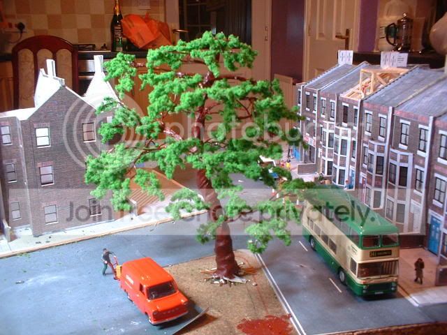
Now that I can 'see' more of the layout I can plan the scenery a bit better. I still need to finish off the houses/shops although I have managed to glue the backs on! At the back of the shops I decided that I needed somthing with a bit of height. So after seeing some trees being made at Darlington exhibition I decided to have a go. This is the result……..


It's still in the early stages and I need to find the proper 'green stuff' but the question is does it look to big ?


Today after doing a bit of job hunting and tiyding up the front garden I made a start on the last two pullman conversions. These comprise of another standard coach and a standard brake. So far I have altered the windows and sprayed the bodies with undercoat then white……..


Once the white has dried I can then add the rail blue around the windows.;-)
Back to the top

Post

Posted
Rating:
#36074
Guest user
good to see your back on track Dave,the tree is not to big and will look fine,
and the train is looking good too.

:pathead:thumbs:thumbs:thumbs:lol::lol::cool:
Back to the top

Post

Posted
Rating:
#36467
Guest user
Hi Dave

sorry about the job, sad time we live in.

Ref. the tree, standing alone yes it does look a tad big. with some greenery added and a couple more trees it will blend in well and will not be to big. the eyes are drawn to the tree as it is the only bit of greenery around.
Back to the top

Post

Posted
Rating:
#36480
Guest user
Another comment thrown in regarding your tree size, Dave.

If you measure it's scale height, I'll bet that it's still not as big as the real thing can grow. I think Matt's answer is correct. Make this your tallest and with a couple at 80% scale size and a couple more at 60% and you'll see a vast difference.
Back to the top

Post

Posted
Rating:
#36920
FS
Avatar
Inactive Member
I like the size of the tree. I think often trees on layouts are too small.


Thomas

TUTTO IN GRIGIO ARDESIA
Online now: No Back to the top

Post

Posted
Rating:
#37068
Guest user
Last week I had my nephew over for the day so we spent the day playing trains in the garage. One plus point of this was that I finished track laying on the Albert dock branch. The past few days has seen a general tidying up of the layout along with the wiring up of the lighting over the TMD and canal sections. Amongst the pressies this morning was a little box containing some small trees/bushes. First thought was to use them on my N gauge layout. On closer inspection I noticed that they used wire for the trunks. Then I had an idea!!! So this afternoon has been spent soldering all the small trees to the framework of the large tree behind the shops. Heres the result….


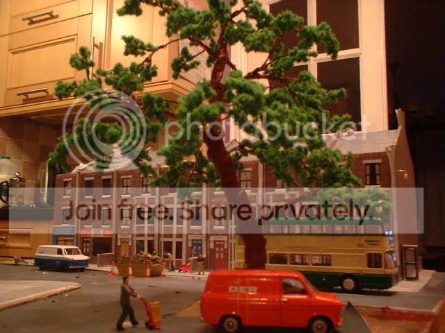
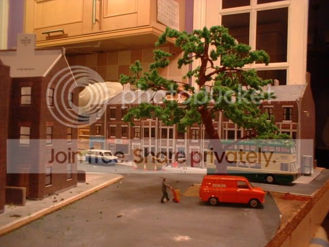
The eagle eyed on here will have spotted the traffic cones around the skip. These have had fiber optic attached so now the tops of the cones light up. ;-)
Back to the top

Post

Posted
Rating:
#37077
Guest user
done ok there then Dave nice pressie,like the cone idea,
all the best for the future.

:thumbs:thumbs:lol::lol::lol::cool:
Back to the top

Post

Posted
Rating:
#37081
Guest user
Nice idea with the trees, Dave. That's come out quite well and now it's a useful addition to the layout.
Back to the top

Post

Posted
Rating:
#37256
Guest user
Thanks guys for all the feedback regarding the tree. I just need to tone down the paint on the trunk now. The past couple of days have been spent doing a few odd jobs! First up I made a set of flashing lights for one of my zebra crossings. These were made from a couple of 3mm leds mounted on some brass posts. To wire them up I experemented with some enamaled copper wire( thanks Owen ). This worked realy well and has given me some ideas with regard to future signal building. This brings me on nicley to the next area signaling! I have built another signal this time located on the viaduct over the canal. This signal is a two aspect red/yellow and controls the entrance to the station area. This signal features a flashing yellow and works in conjunction with one of the signals on the gantry outside. When completed the railway will have two modes of operation. In 'run' mode the railway will operate it'self with trains bypassing the terminus and running continusly around the garden in sequence thanks to the automated storage sidings. In this mode the flashing aspects are used for the long crossovers that access the return loop. The gantry signal shows a flashing double yellow whilst the new signal shows a single flashing yellow. In reality this signal would posably have a feather indicator on the top instead of the flashing aspect but making one looks to be a pain! In the normal mode the signals show steady aspects with the one on the bridge being held at red and controled by a push button on the control panel. Moving up the line slightly I have refitted the point under the road bridge next to the traffic lights. Now the point has its motor fitted and the 'duff' piece of track under the bridge sorted out scenic work on this area can continue. A while back I laid some balast on the station approches. This is in the process of being removed( lucky it wasn't stuck down!) so that the wiring of the track can be sorted. With a trackplan as complicated as mine I decided to keep the wiring as simple as posable. So I plan to install some relays between the tracks that will be used to switch the point frogs and power supply. Once finished they will be hidden with a building. This keeps the wiring to a minimum with the relays being controled by the switches on the point motors. I have already used this methord of wiring on the return loop to the garden with great sucess the relay being mounted on the baseboard top and bare copper wire running between the tracks. The wiring was buried under the balast and the relay is due to be hidden under a platelayers hut! Once the station approch area is sorted out it will be posable to run some trains again !!! :thumbs
Back to the top

Post

Posted
Rating:
#37280
Avatar
Full Member
Looking good,Dave.That tree will look perfect with the trunk 'greyed down'.The height is fine,and it fits the space perfectly.
All the best with the job hunting.

cheers,John.B.
Online now: No Back to the top

Post

Posted
Rating:
#37808
Guest user
Well here we go with the first update of 2009!

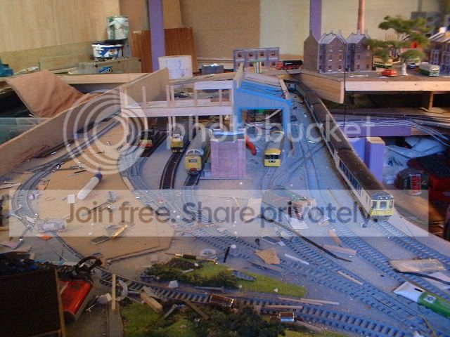
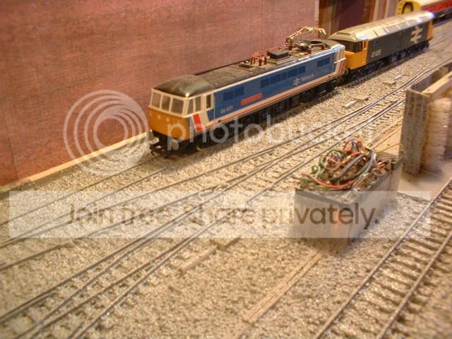
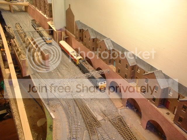
Before I start it would proberly be a good idea to stick up a track plan of the area being worked on so here it is….


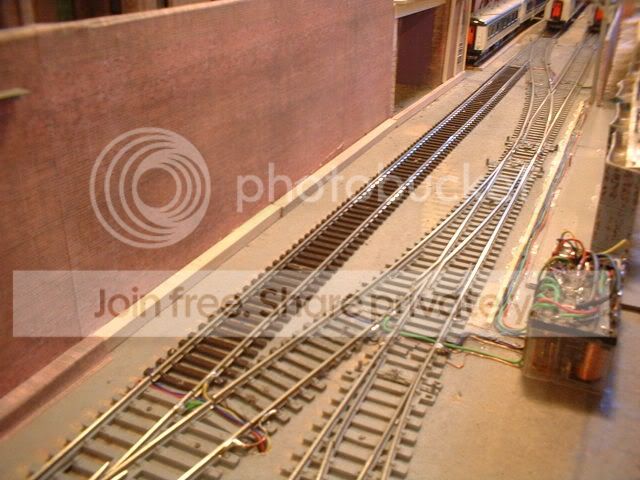
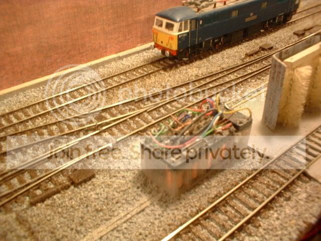
This is the approch to st Davids station with the crossovers and junctions all squezed into a cutting roughly 1' wide! When first laid the track 18 months ago I used a lot of old hornby set track points and a dimond crossing to get the arrangement needed. Once the track was wired and test running started I suffered a lot of derailments due to the state of the track and the sharp radius of the pointwork. One of the first 'improvements' made once I got back into work was the replacement of the track. The junction with the dimond crossing was removed and replaced with a series of crossovers using the longest points that peco produce. Not contented with using very long points I also oppted to use live frogs! Needless to say that wiring has been intresting! By now most of you will be fimilar with the basic layout and opperation. As trains enter the garage thay pass a junction before crossing the canal. This junction is one end of a 'chord' that links the inner loop to the down main line. Now normaly this loop is operated as a simple oval with the station at one side and the tmd at the other but when the 'chord' is switched in it becomes a return loop to the garden. So not contented with having to deal with electrofrog points I also have a reversing loop aswell. Well I did say the wiring was 'intresting'! It has taken 12 months for me to get round to wiring the layout as I kept finding myself sutiable distractions but the time has come to bite the bullet. The answer has been to use some relays to do all the switching for me. So all the trackwork in the cutting has been lifted, loose balast removed, all the rail joiners removed and the track relayed. Now without the rail joiners every piece of track is electricaly seprated! First job was to glue four DPCO relays to the baseboard next to the crossovers. Two of the relays switch the frogs on the crossovers (one relay per set of points) while the other two are used to change over the power feeds to the track sections. The wiring between the relays and track runs on the top of the baseboard and will eventualy be hidden with the balast while the relays themselves will be covered with a building. The eventual solution has turned out neat and tidy as the next pic shows……


The wiring that disapears into the distance runs up to the other crossover and will be covered to make it look like 'cable trunking'! Here is the wiring at the other end….


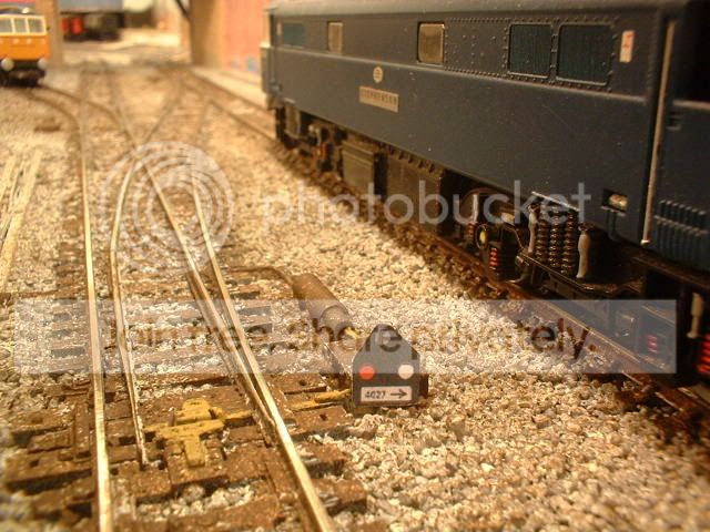
Where rails need to be electricaly connected I have bridged the gaps with copper wire this having the added bonus of making the track supply reliable. The relays are switched in pairs and will be operated via the contacts on the point motors once I can afford to get them! I proberly could have used 4 pole relays but a. I didn't have any and b. this next pic shows the amount of links crammed into a small space!


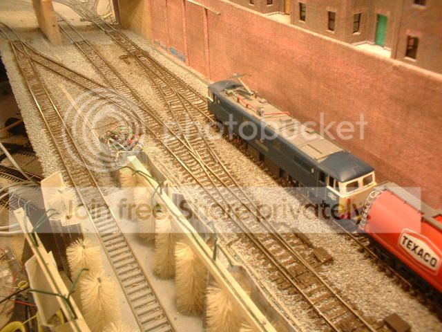
The two thicker black wires are the feed from the controler to the down line. Last night I made one of those 'exectuive decisions' and decided to bin the two thirty year old hornby controlers and instead use my gaugemaster panel mount that got 'nicked' off my N gauge layout. The eagle eyed on here will notice another relay next to the four control relays. This switches the power for the section of track between the crossovers giving me someware to stable locos during shunting moves. The relay switches power to both rails ensuring that I get no short circuits between the controlers. The section of track mentioned is the new black piece in the next pic…

 
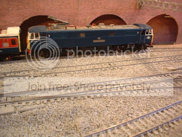
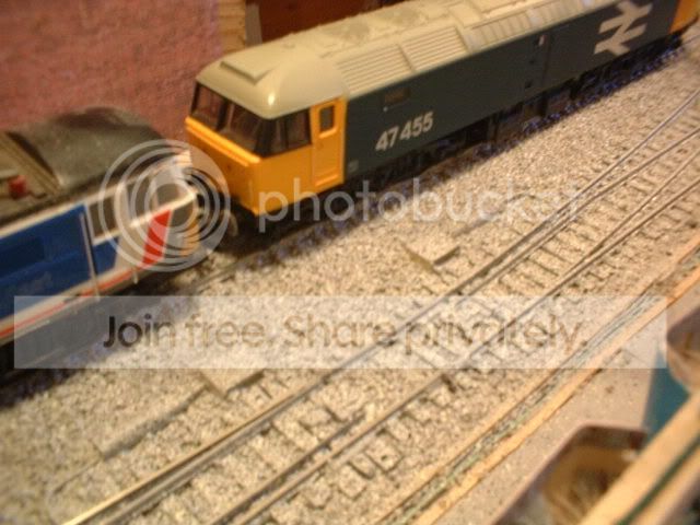
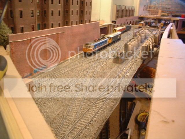
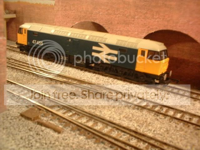
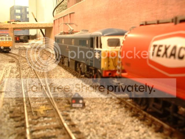
The pics dont realy give a sense of scale but this section of track will hold two mk2 coaches as seen here being overtaken by a class 45 test train…


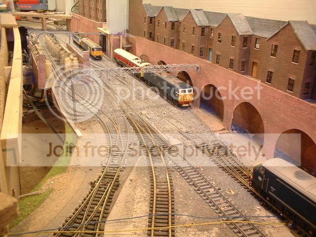
This test train kept me amused for about half an hour last night just running from the buffer stops on platform 1 to the overbridge just before the canal area. The choice of loco is deliberat as it's got the longest wheelbase whilst the tanks have all been rewheeled with lower profile wheel sets so if anything will derail garanteed it will be them! This last shot shows the relays mounted in the space between  the washing plant and the main line……


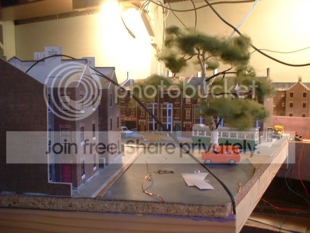
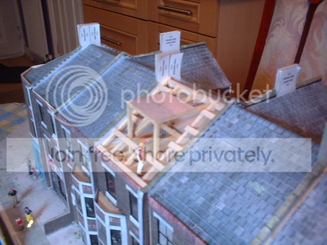
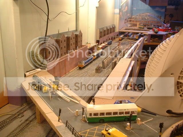
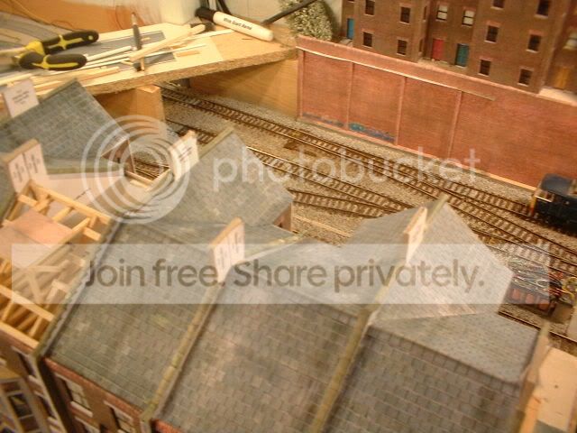
The two points on the left that form the crossover between the main line and the loop have had wiring added so that the points no longer provided any switching. Those working with DCC will understand as this is used to keep all the track live. Also worthy of mention here is the lower sidings just visable at the left. The scenic section that I have been working on fits to the left just out of shot whilst the traffic lights are located just off the bridge. Once the work on the electrics is finished attention will turn to the bridge itself and the embankment between the railway and the back of the houses/shops. ;-)
Back to the top

Post

Posted
Rating:
#37933
Guest user
A late night shift on the railway last night has made way for a transformation today. I refer of course to that modelers favourite balasting!! Before tackeling the dreaded task I had a go at scratchbuilding some dummy point motors. I began by looking through some railway books and noting the general design. A rumage through a box of old electronic components produced some old square capacitors. These had one leg removed and then glued next to the point with the remaining leg positioned over the tie bar. Great I thought thats the gearbox linkage sorted. Next the motor assembly itself. For this I cut some plastic tube then fitted some smaler plastic tube inside. Through the middle I pushed a length of copper wire. The motor was then glued next to the gearbox. I then added some more cable ducts made from matchsticks and ran some scrap cable from the ducts to the point motors. Then came the balast. For this I have been using fine fish tank gravel that is sold in big bags for not a lot of pennies and at the end of the day us modelers paint over the stuff anyway! The balast was laid using a clever spoon that had a tube for a handle. This was part to a set that also contained a dropper that I got from a local morisons for 99p. Once the balast was in place I decided to glue it down so out came the PVA. This was mixed the usual way and then applied using the dropper. Then at 12.45 I retired to bed and left the white goo to dry. This morning I checked and it's dry! So the trackbed had a coat of grey primer then a coat of stone effect paint. Heres the results……


Back to the top

Post

Posted
Rating:
#37939
Guest user
Sorry for the double post. :oops:

I think my internet is playing up again as I posted it the first time went over to TVGR then when I came back here the post wasn't in the thread so I reposted it and now theres two! Very strange. :roll:
Back to the top

Post

Posted
Rating:
#37968
Avatar
Legacy Member
No problem Dave.
Online now: No Back to the top

Post

Posted
Rating:
#37977
Guest user
Thanks Bob for sorting that little problem! ;-)

After the paint had dried I decided to have a go at painting the track with some brown acrilic paint. The result is as follows….


Next on the list will be scratchbuilding some ground signals!
Back to the top

Post

Posted
Rating:
#37978
Guest user
those point motors are smart ,good thinking batman, methinks robin
will now copy that idea …

:hmm:thumbs:thumbs:thumbs:lol::lol::lol::cool:
Back to the top

Post

Posted
Rating:
#37979
Sol
Guest user
Dave, based on the first set of photos showing the ballast result- my thought was YUK  but then after painting - better now - looks good. I too like those expensive point motors.
Back to the top

Post

Posted
Rating:
#37985
Guest user
Thanks Ron for being honist! The first pics didn't show the fleck spray up very well. Painting the track a sleeper at a time took a while but the end result is quite effective. To make the balast look deeper I just used less paint on the sleepers. Now that its painted the point motors stand out realy well. The examples that I am copying off have a white box on legs next to the motor. These still have to be added but I think that what I have so far looks convincing. Ok honist opinion time again. I am building some shunting signals. After cutting up some plasticard and drilling a couple of holes in I managed to make a working signal but I couldn't get the look quite right. Then I had an idea copy and paste. So I right clicked the image from Chris's signal thread imported it into some photo software, shrunk it and printed. Once I have the size sorted I can laminate them then stick them onto plasticard then drill out for the fiber optics. So heres my first attempt. I just need to know if the size looks ok?


heres a closer pic….


Back to the top

Post

Posted
Rating:
#37991
Sol
Guest user
Dave, that shunt signal size looks just spot on.

Ballasting - I always paint sleepers & rail first, apply ballast but do not leave it over the sleepers ( though there are bits that show up in photos, to be removed) & end up like this


Back to the top

Post

Posted
Rating:
#37993
Guest user
That's amazing the balast in you pic looks exactly the same as the gravel that I got from the pet shop before it was painted, etc. :shock:
Back to the top
1 guest and 0 members have just viewed this.