00 Gauge - The Heatherburn Garden Railway.
Posted
Guest user

The lower lines have been omitted for clarity.
Posted
Full Member
That is a plan and a half. The wiring must have been interesting! It all makes sense now, when I look at your pictures. Thanks for showing this.
Bob(K)

Posted
Guest user
How do you access the inner part of the layout in the garage are there step over points you use ?
cheers Brian
Posted
Guest user
Posted
Guest user
After waisting a whole day trying to get the webcam working i've given up for the time being. At least I didn't damage the cat5 cable whilst pushing it through the cavity wall! Just need a new keyboard now as this ones nackered!!! Hopefully more progress on the layout tomorrow.;-)
Posted
Guest user


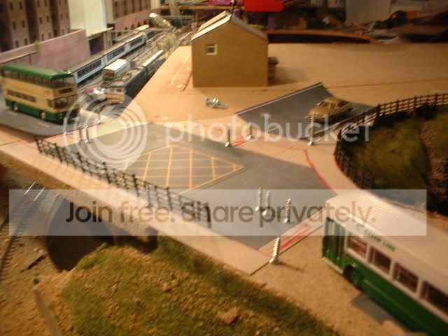
The empty tin Im thinking of using as the basis of a storage tank although plan B is to use the area as a car park.

The base of the scenery was built up from polystyrene sheeting stuck together using my favourite stuff decoraters caulking. This stuff is great for sceneary building and is only £1 a tube from poundstreachers! The roadway was made from thick card stuck in place with the caulking and then painted with stone effect paint. The grass matting is stuck with…. caulking along with the bushes……..


Somewhere under the pile of junk in the background is the TMD! Just as well that the building uses 12mm thick chipboard for the main walls!:lol:
Posted
Guest user
a good bit of info, i have tubes of it.
:doublethumb:lol::lol::lol::lol::lol::cool:
Posted
Guest user

Looks terrific!
Mike
Posted
Guest user
Posted
Guest user
Just incase you hadnt notice your tank is upside down ! LOL
(Im guessing thats because it doesnt have a lid !)
Posted
Guest user

Then as always I got sidetracked!


Needless to say today whilst on my travels I have been paying extra attention to sets of traffic lights! I have a basic plan in my head that all depends on my old comadore 64 working? Why you may ask? Well a few years back I came up with a use for the old computer. So instead of being a doorstop I used it to control a set of traffic lights. This was done using the user port on the back of the computer. I found that by writing a simple program (anyone remember basic!!) I could switch leds on and off. So I wrote a program that would control 8 leds. 6 leds formed two sets of traffic lights whilst the 2 others were used for the pedestrian crossing(red/green). I managed to get the correct sequence for the lights and even managed to get the ped green to flash! That was as far as I got for not long after we moved house (twice) and the computer got dumped in the garage. Luckly the tape is still in the data recorder with the program on cos after five years I carn't remember how I did it! First job tonight is to make a cable for the TV and see if this old piece of junk still works. Watch this space!;-)
Posted
Guest user
If they do you could open up all sorts of little cameos, ie. "I only said blow the ……"
Posted
Guest user

Right Im off now before I spend all evening on here again!;-)
Posted
Guest user

Now heres one for the electronics wizz kids out there. The 64 has 8 outputs that switch 5v on/off (TTL?) I need to connect multiple leds to each out yet the outputs dont supply enough current to drive more than 1 led at a time per output. Are there any circuit diagrams about that will enable me to do this? :hmm
Posted
Guest user
http://home.cogeco.ca/~rpaisley4/20step.html
There maybe many others in this site overall.
Posted

Legacy Member
Posted
Guest user
or can you use lower voltage LEDs in series?
Posted

Inactive Member
or can you use lower voltage LEDs in series?
if you use LEDs in series, if one blows, the lot go out and it is a job to find the crook one.
Max
Port Elderley
Port Elderley
Posted
Guest user
Posted
Guest user
Thats a very good point !!if you use LEDs in series, if one blows, the lot go out and it is a job to find the crook one.
1 guest and 0 members have just viewed this.