00 Gauge - Maxmill Junction
Posted

Site staff
Petermac's Railway
Peter, the side mounted solenoid should be OK on 12vDC but adding a microswitch will put an extra load onto it & it may not work. You could use the same CDU you plan to use for the fiddle/storage yard.
Ron
NCE DCC ; 00 scale UK outline.
NCE DCC ; 00 scale UK outline.

Posted

Full Member
As I understand it, trhe CDU follows the power unit and runs on around 16v AC. From there, the feed goes through the switch to the PL11 with it's micro switch - (not sure how I'd add LED route indicators)
That would mean that, mixed in with all the 12v DC DPDT Tortoise switches, would be an odd SPST switch running on 16v AC …………………….. :???:
Or am I wrong …………………………?
'Petermac
Posted

Site staff
:cool wink
Wasnie me, a big boy did it and ran away
"Why did you volunteer ? I didn't Sir, the other three stepped backwards"
"Why did you volunteer ? I didn't Sir, the other three stepped backwards"
Posted

Full Member
I maybe a bit late but here are a few comments/suggestions
Tortoise Surface mounted as Matt suggested…….is probably the best solution. There is a kit you can buy or you can improvise something. You look as though you have sufficient space to set it back on the base board and conceal it with a building
Conventional Surface Mounted Peco Solenoids you can put a peco double switch on top which will handle polarity and the LED indicator. I have never set them back beyond the reach of the Peco mounting base but I believe it has been done. Using the base makes concealment more difficult but it can be done.
 o
oSide Mounted Peco will obviously work but I agree with Ron….in my experience they rarely have the power to throw the point and a micro switch
However they can work with these
Accessory Decoder CDU Solenoid Drive SX 2-Way with Power-Off Memory and Protective Case
These guys have a built in CDU, draw power from the DCC bus not the accessory bus, switch polarity and have contacts for manual switches and LED……..because they are hooked to the DCC bus you can also use the DCC throttle to throw them……they will work with any solenoid (not stall motor)
As you know I use RR&Co as a virtual switchboard and dont have any manual switches or LEDs but for what its worth the vast of my point motors (both Peco and Tortoise) are powered by a single 16v AC bus
Hope this helps
Best Wishes
John
Posted
Full Member
I suspect I may end up separating control of this section of the yard from the mimic panel and use my solenoid motors without the LEDs.
I'm probably being stupid but I have several methods of operating points at my disposal - DCC via the Lenz LS150, the Megapoints servo system and the conventional flicking switches method.
I opted for the "flicking switches" method on this part of the layout because, being hidden from view, I felt I needed the physical throwing of the switch and route indication offered by the mimic panel to avoid too many mistakes in a difficult to access area. I could have used the Megapoints system instead but wanted to hang on to the servos for use on the upper deck where clearance would be a problem for the Tortoi.
My initial intention was to change all the insulfrog points for live frog. Given the number of points on the layout, together with their positioning, I have decided against that and will fit stay-alives instead.
'Petermac
Posted

Full Member
Great progress Maxmill…
As a possible help for your control panel the story of my Llandyfroig Junction panel starts here…http://yourmodelrailway.net/view_topic.php?id=362&forum_id=21&page=67#p246828
and there is a wiring diagram for the way I did the LED bi-directional panel lights here… Note that I use SEEPS and a relay (S4442) to get both Panel LEDs and frog polarity happening from a single switch throw.
http://yourmodelrailway.net/view_topic.php?id=362&forum_id=21&page=71#p255600
… I'm pretty sure that the minor mods mentioned to the LED setup is that instead of having a resistor on the output of the bi-directional LED I had to have a resistor on each individual input to the LED. The resistors being different values for red and green to get a similar intensity of light from the red and the green. That is, if I used the single resistor on the output the LED brightness between RED and GREEN was markedly different. By putting different value resistors on the input wires I could adjust the brightness by swapping out a weaker resistor for a stronger one, or vice versa.
I made up a test unit with crocodile clips to hold the resistors and fiddled until I was happy.
I was a total electronics numpty (still am) but it was great fun to research, experiment and complete.
Hope that gives you some ideas.
cheers
Marty
Posted
Full Member
The very mention of the word "relay" takes me back to my school days passing a rolled-up newspaper to the next lad on the circuit ………………….but I suspect you were talking about something else …………. :hmm
'Petermac
Posted

Full Member
D
'You may share the labours of the great, but you will not share the spoil…' Aesop's Fables
"Beer is proof that God loves us and wants us to be happy" - Benjamin Franklin
In the land of the slap-dash and implausible, mediocrity is king
"Beer is proof that God loves us and wants us to be happy" - Benjamin Franklin
In the land of the slap-dash and implausible, mediocrity is king
Posted
Full Member
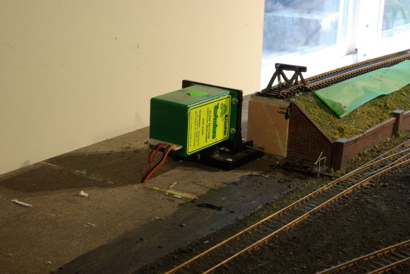
Having thought long and hard about that troublesome point over the timber bearer, I decided to use a Peco side mounted motor in conjunction with a Gaugemaster GM 500 polarity switcher. I'm guessing these are very similar to the Hexfrog Juicer, one of which I have in stock but wanted to hang onto that for another potential problem area. I am currently awaiting delivery of a triple pack of said GM 500s.
Space restriction prohibited any kind of remote operation of a Tortoise - they are just too big for the site in question.
Trains can now run from the fiddle yard around 3 walls of the unit - only the link across the doorway remains to be sorted at which time, I will have the inner circuit completed.
I did have a few frustrations in firing things up. I had no idea how the existing layout had been wired except that most of the feed wires seemed a bit on the slim side and they were soldered to rail joiners. Facia mounted copper tape acted as the bus - apparently a favourite method of ZTC.
After some resoldering and more than the occasional short circuit, I managed to get the 3 sides up and running using an old Hornby DC controller - for testing purposes. Next morning, wanting to show off my handiwork to Liz - a roll of drums and naturally it failed !! The loco stopped half way round. After much poking and sweet-talking to the electrics, it burst into life………….. temporarily !!! In the end (and the "end" was still some way off) , the problem turned out to be the old controller itself so I could have saved myself several hours of soldering, some carefully chosen words and painfully seized muscles from getting up and down from under the baseboards.
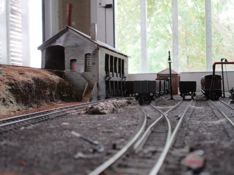
A few photos to remind myself what it's all about.
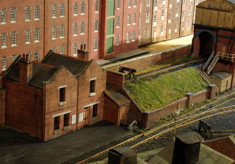
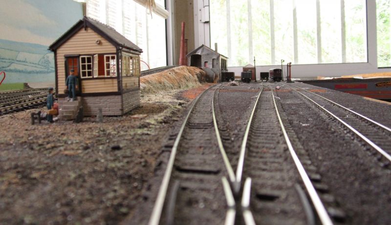
The roads heading to the coaling shed with the small signal cabin controlling it all:
The coaling shed clearly showing the damage caused in transit during delivery of the unit. The backscenes, which I had been assured were frimly fixed to the walls, fell inwards causing quite a lot of damage to any structures I was unable to remove. Once I take the roof off, it will be a relatively simple task to add a further layer of card to the inside of the gable.
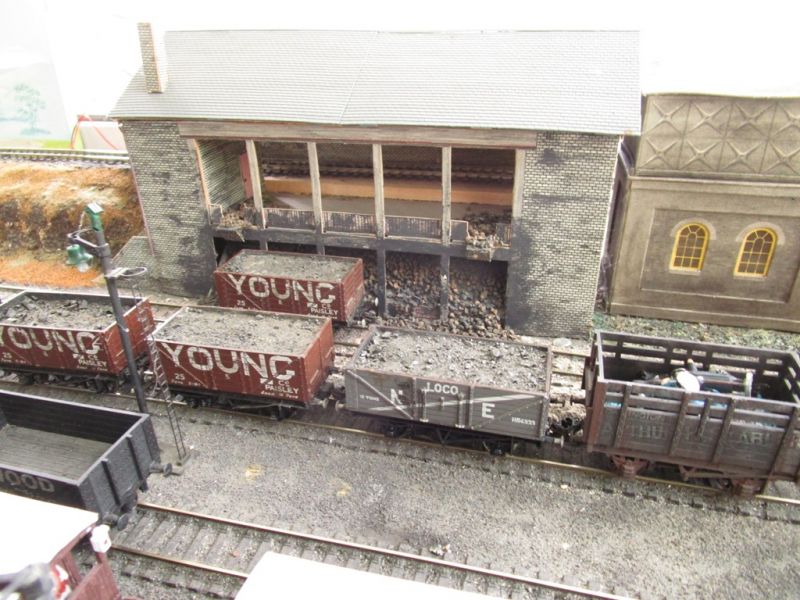
Loaded wagons awaiting collection. It appears the first "Youngs" wagon has jumped the rails ! The one on the right is an ancient Hornby wagon still awaiting a wheel change and Kadee couplings:

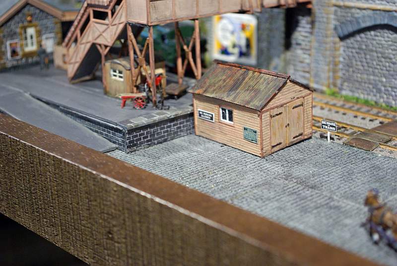
The business side of the shed with some rather large lumps of coal !!
'Petermac
Posted
Full Member
Phil
Posted
Full Member
So good to have some progress. Do you have another DC controller to continue testing with?
Posted
Full Member
I do have another DC controller Marty - in fact, 4 of them !! An old H & M Duette, the 16v output from which drove my SEEP motors on the old layout, a Gaugemaster twin track which came with this unit and 2 Gaugemaster panel mounted controllers which came from John Dew. All work perfectly but, when initially required, were in boxes "somewhere" !! Failure of the Hormby train-set controller forced me to search for the correct box and my word, I hadn't realised just how much "stuff" I've got stored in boxes ……………………..
I encountered another trying problem today. One I've never come across before but others may have.
I was adding more droppers and in the process, wired up another point - a Peco medium radius live frog. All was OK until I set the point for the turn. A short ! I persuaded myself that, in spite of working in one direction, the short was on the frog so ease my hulk back under the baseboard and reverse pins 2 & 3 on the Tortoise. No, certainly not that !! After much head scratching, testing with a multimeter and yet more choice words, it appears that the problem was because the rail gap, where one removes the little link wire for "DCC friendly" wiring, was so tight that any downward pressure on the centre of the point, closed up the gap thus creating a short. The gap is usually quite small but on this point, it was hardly visible and presumably I'd pinned the centre area too tightly creating a slight concave curve of the whole point thereby closing the gap on one rail. I pin all my trackwork until it's ballasted at which point, I remove the pins.
These "unusual" and random electrical problems certainly cause me a some serious headaches - almost enough to push me back to RC model boats - almost, but not quite !!
'Petermac
Posted
Full Member
I think congratulations are in order…..Running trains has to be viewed as great progress. You have my sympathy with the failed demo for Liz…..there is a certain inevitability about these things. Before I video one of my routines I test and test until it is fault free then ask Doreen down so I can show her…..invariably a new hitherto undetected fault emerges……it is now an established part of my testing routine!
The GM 500 may perform the same function as the frog juicer but I think it works in a different manner, regardless it looks like a great piece of kit and so inexpensive. I wish I had known about it years ago. Do let us know how it works out. The Peco switches I initially installed, before opting for tortoi, are failing one by one and they are always inaccessible….this looks like a much cheaper solution than the DCC Concepts product.
Best wishes
John
Posted

Full Member
Michael
Posted
Full Member
I have today succeeded in connecting up the first circuit - the "up" line (inner circuit), currently in test mode so running on DC.
This however, is not the first time I've circumnavigated the unit with "live" trains - it's the third time in as many days, hence my initial comment about planning.
The repeated problem was the long curve crossing the lift up flap. The first attempt worked quite well - until I tried to place the Bachmann 4 road engine shed where it belongs. The new circuit was too close to the rear corner of said shed and a full length coach just touched the corner of it. Moiving the latter back slightly was not possible because the ash pit on one of the roads would have then almost been inside the shed.
As the Bachmann shed is "modern image", I did consider moving it on to a more modern owner but, as the yards and tracks are laid, the inspection pits in place plus, I do rather like the buiding, decided to keep it and re-lay the circuit (there's that "re-lay" word again !!)
The second attempt solved the shed proximity problem but resulted in a very tight corner on the opposite side on the unit. In fact, too tight for a main through line so it all came up again.
Today, at the third attempt, I'm happy with it - everything fits and, although there is a very short stretch with a 24" curve, it will be hidden by infra-structure and I'm pretty sure most of my stock will negotiate it. I have had to place the curve slightly closer to the outer walls than I'd hoped - the track rising to the upper level may now have to cross it on it's viaduct rather than run alongside and behind, but that's a situation for another day.
I will have to ensure I carry on with the laying of track rather than testing trains over the next few wet days. I still have droppers and point motors to fit but I'm awaiting a delivery of "bits" from UK before I can complete that chore.
'Petermac
Posted
Full Member
Michael
Posted
Full Member
The rain continues today so I thought I'd have a fix of loco sounds………… :roll: I dug out my Lenz 100 DCC system and populated the layout with some of my better locos.
Whilst it was indeed fun, it highlighted some problem areas around some of the existing insulfrog points, presumably caused by bouncing around on the back of a lorry when it was delivered. Rather than trying to find out what is causing the derailments (in one direction only), I've decided to bite the bullet and swap the offending points for electrofrog units.
Yet more corrective work to do but it won't get better on it's own………………………………….

It was however, great fun testing the sound locos after such a long absence. :thumbs
'Petermac
Posted
Full Member
Despite the problems it must have been great to have your favourite locos running again. I suspect you have made the right decision replacing the insulfrogs………better to do it now than after ballasting and scenery are complete and you finally get fed up with random derailments……..how do I know this?
Best wishes
John
Posted
Full Member
I had hoped to avoid changing the points on the right hand side of the unit but I fear this may not be possible in some situations. If I have running problems now, they can only get worse as time goes on………………..
It was great to have my DCC locos running again - the only problem was, I spent well over an hour "testing" when in fact, I ought to have been concentrating on trackwork ……………. Still, rain is forecast again for tomorrow ………..it's odd but I'm actually hoping the sun doesn't shine for the next few days ……………. :roll: :roll: :roll: :cheers
'Petermac
Posted
Full Member
For anyone interested, they are quite small - shown here with a OO Gauge coach and track for scale. There are 9 terminals on each unit - all solder tabs leaving the user to wire up those required.:
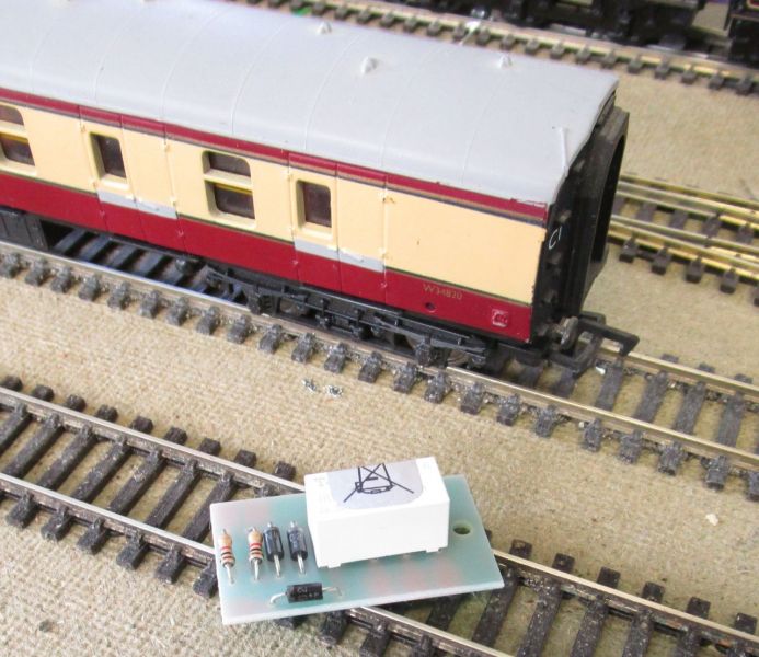
I bought a pack of 3 although at present, I only need 1. The wires serve the following functions:
Purple wires - 1 to + rail on the track and the other to the - rail.
White wire to the frog
Red, Green and black wires to the point motor and passing contact switch
Brown, Orange and Blue wires are from an additional switch function for signals or route indication (if required).
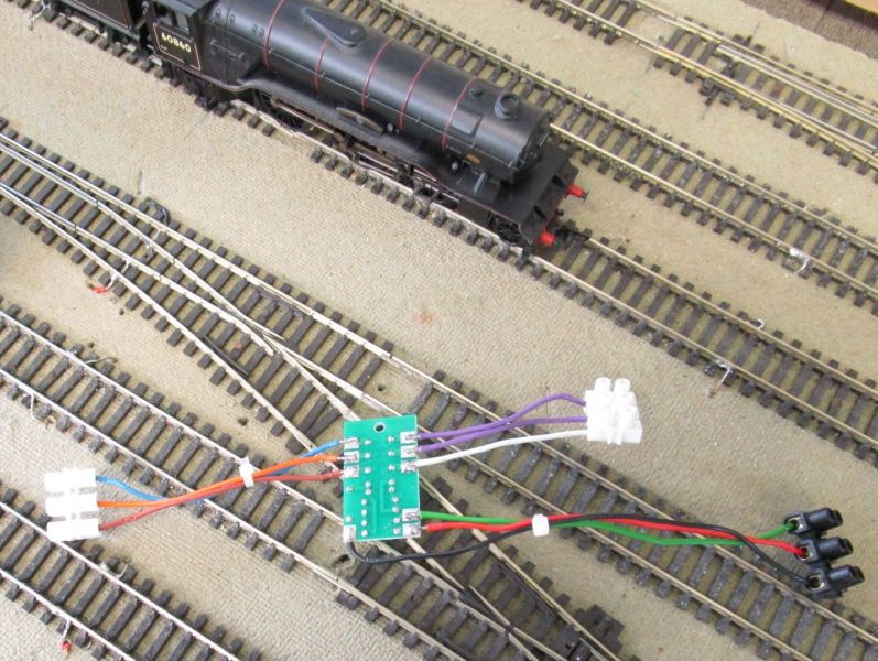
The unit will be fixed under the baseboard via the hole in the paxolin board in the vicinity of the point it controls.
'Petermac
1 guest and 0 members have just viewed this.