00 Gauge - Maxmill Junction
Posted

Full Member
Petermac's Railway
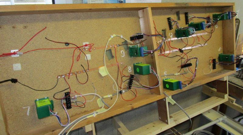
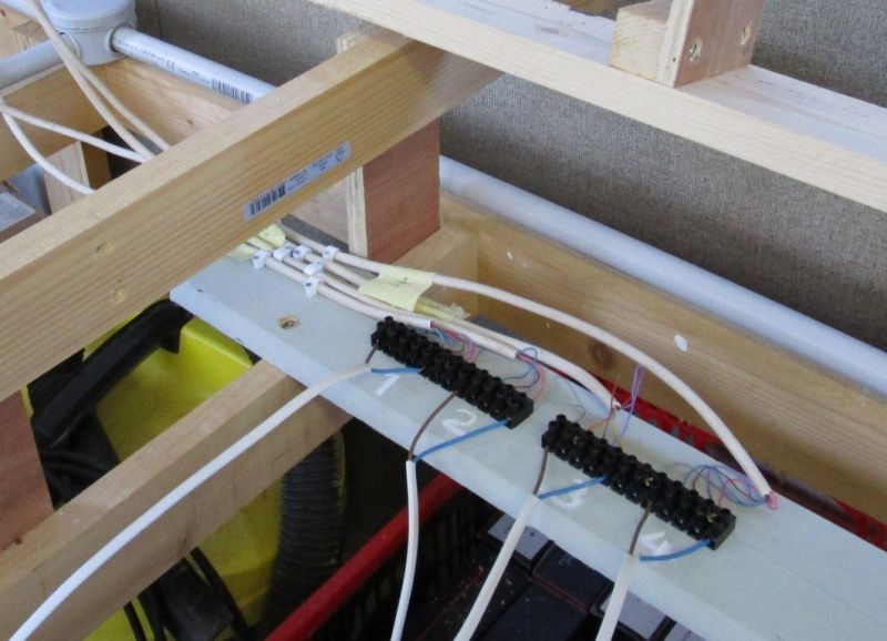
The first bank of Tortoise motors installed at one end of the fiddle/storage yard. They now need a flying lead to connect to whatever system I decide on to control them.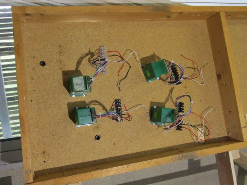
Similarly, the track feeds are starting to take shape. Again, because the "control area" will be on a horizontal board below this (to allow all soldering etc. to be done on the flat), I'll connect it all with flying leads.
I'm thinking along the lines of RJ45 telephone cable but not sure if it is "meaty" enough. I think telephones worked on 20v so voltage should be OK although the current draw might be too heavy ………………… What's the consensus ?
'Petermac

Posted

Site staff
Ron
NCE DCC ; 00 scale UK outline.
NCE DCC ; 00 scale UK outline.
Posted
Full Member
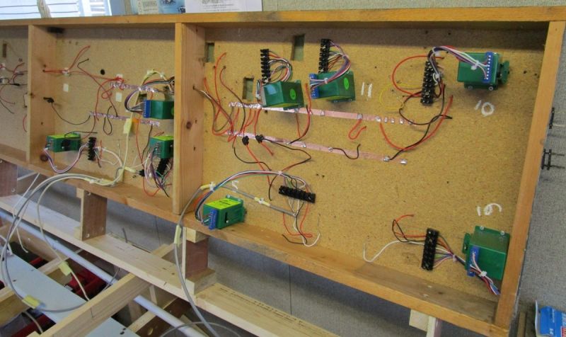
All the point motors are in place and the next job is to run cables from them down to a mid-point junction area. For this job, I'm using RJ45 telephone cables - 5 wires from each - which will then be linked to the control panel which will hinge on the front of the layout.
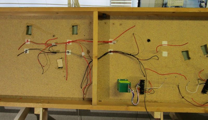
The underside of the board showing the motors and some of the connecting cables (the heavier white cables)
The mid-way connections are situated, just off screen, on the light green plank at the bottom of this picture:
Here - (out of focus !) - are the choc blocks showing the incoming telephone cables. Further cables will then connect to the mimic panel on the front of the layout at this point. The twin cables are a temporary attachment to allow me to test all the motors with the board in place. Some of the points will move in tandem where they operate a crossover. Testing will ensure that these points move the right way and that all frog polarity is correct before finally fixing the board down. I use a 9v battery for testing. The track will temporarily be connected to a DC supply (simply because I happen to have a DC polarity tester ………..)
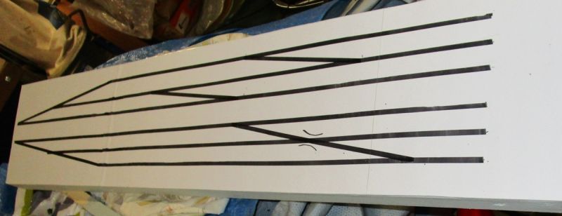
The mimic panel will have all the switches and LED route indicators and will hinge onto the front of the layout. At present, only a part of the trackwork is marked because I'm not entirely sure what happens beyond the tracks marked !!!
'Petermac
Posted

Full Member
That said Peter, it is significant progress and executed with a well considered plan and as photographic evidence confirms, with a neat and workmanlike application. Well done that man and I wish you good fortune with the testing process.
Best,
Bill
At 6'4'', Bill is a tall chap, then again, when horizontal he is rather long and people often used to trip over him! . . . and so a nickname was born :)
Posted

Site staff
Ed
Posted

Full Member
I am fascinated to find out where the tracks will head to. :lol:
Best wishes
John
Posted

Full Member
Great job all round. Craftsman!!
Michael
Posted
Full Member
All very welcome comments - "well considered plan", "coming on well", "neat and workman like", "neat and elegant wiring" - yes indeed, very welcome comments however, I think you've posted in the wrong thread …………… :oops: :oops: :oops:
I had planned to make my wiring as neat as possible - I recall when we restored this old barn we now call home, we had to have the new electrical installation checked before they'd give us a permanant supply. When the inspector took the cover off the rather large fuse box they tend to use in France, he turned to our electrician and asked if he'd worked in the aerospace industry ………………we're not that far from Toulouse where Airbus Industries are based. His wiring was an absolute picture.
I thought "if he can do it, so can I". How wrong I was. It is indeed much better than Maxmill Mk1 was but still not as neat as it should, or indeed, could be.
I'll be very pleased when this section is completed and I can get on with building a layout. I hadn't envisaged it taking anything like so long nor being so fiddly.
'Petermac
Posted
Full Member
Well it is a fiddle yard Peter, so expect fiddly!
Crack on!!!
Bill
At 6'4'', Bill is a tall chap, then again, when horizontal he is rather long and people often used to trip over him! . . . and so a nickname was born :)
Posted
Site staff
I am like a plumber with leaking taps or a furniture maker with wobbly chairs; the D&S ain't pretty under its skirts but it works…
Ron
NCE DCC ; 00 scale UK outline.
NCE DCC ; 00 scale UK outline.
Posted
Full Member
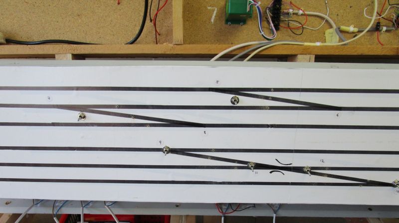
Having fitted the Tortoise motors, together with their 8 wires each to the fiddle/storage yard, I started fitting the switches to the control panel - this panel:
1 switch for each "standard" point, 1 for each of the 2 crossovers and a further 2 for the double slip - 10 switches in total. This panel will hinge on the front of the layout and is therefore kind of "wedge shaped" to allow for quick, easy visuals and switch access.
I'd drilled all the switch holes, mounted all the switches and soldered the first wire between each switch and a pair of 28 terminal tag strips when I discovered I'd drawn the track plan upside down !!! The only slight positive is that I hadn't drilled the smaller holes for the LED route indicators.
Left as is, when mounted, instead of having an upward facing slope, the slope would now face downwards. :twisted: :twisted: :twisted: :twisted: :twisted: :twisted:
I'll have to remove all the switches, re-cover the board with fresh adhesive white plastic "Fablon" type material, hope the incorrectly drilled holes don't interfere with the new switch placings and start all over again. If the holes do get in the way, then it's a complete rebuild of the panel ……………………..Grrrrrrrrrrrrrrr
'Petermac
Posted
Full Member
Sorry Bill - I meant to reply to this when you first posted - your comment made me laugh out loud - I hadn't spotted it at all …….." I am making slow progress on the new storage/fiddle yard area - I hadn't envisaged it taking anything like so long nor being so fiddly "
Well it is a fiddle yard Peter, so expect fiddly!
Crack on!!!
Bill
'Petermac
Posted
Full Member
I'm feeling annoyed, frustrated and generally, not a happy bunny !!!!!
Having fitted the Tortoise motors, together with their 8 wires each to the fiddle/storage yard, I started fitting the switches to the control panel - this panel:
1 switch for each "standard" point, 1 for each of the 2 crossovers and a further 2 for the double slip - 10 switches in total. This panel will hinge on the front of the layout and is therefore kind of "wedge shaped" to allow for quick, easy visuals and switch access.
I'd drilled all the switch holes, mounted all the switches and soldered the first wire between each switch and a pair of 28 terminal tag strips when I discovered I'd drawn the track plan upside down !!! The only slight positive is that I hadn't drilled the smaller holes for the LED route indicators.
Left as is, when mounted, instead of having an upward facing slope, the slope would now face downwards. :twisted: :twisted: :twisted: :twisted: :twisted: :twisted:
I'll have to remove all the switches, re-cover the board with fresh adhesive white plastic "Fablon" type material, hope the incorrectly drilled holes don't interfere with the new switch placings and start all over again. If the holes do get in the way, then it's a complete rebuild of the panel ……………………..Grrrrrrrrrrrrrrr
Oh dear! Don't you just hate it when that happens?
To give you another positive….. you have made a fellow modeller - me - somewhat relieved that I'm not the only one who makes mistakes, for which I thank you! My mother was an artist, and when she got things wrong in her painting she would always say…"They don't give you a harp in Heaven for ranting and raving…." So consider it soul making!
Hope all goes well with the re-fit
Michael
Posted
Site staff
my main Tawnton panel is the "final" version after at least 4 before it !
"Model rail is FUN"
Ron
NCE DCC ; 00 scale UK outline.
NCE DCC ; 00 scale UK outline.
Posted

Legacy Member
My view is anyone who claims they dont make mistakes is one of two things.
They are are not human and are a robot or they are a liar.
Brian
OO gauge DCC ECOS Itrain 4 computer control system
Posted
Full Member
Whilst I appreciate your comments about mistakes being natural, character forming, part of a learning curve etc. I know, having specifically designed the panel to be an "easy view" facia, it was stupid of me to make such a mistake.
The fact that you've made at least 4 renditions of your Tawnton panel Sol, does little to appease me - all I can say is that, when you've had a little more practice with wires, you'll get it right next time ………………….

I spent this afternoon rectifying the mistake - in between watching the rain lashing down and the level of the floods in the neighbouring fields steadily rising - all because the darned jet stream has shifted south - this lot should have been quenching UK's thirst……………..
'Petermac
Posted
Full Member
On the old Maxmill, I had used either the Lenz LS150 accessory decoders or, in "local" areas, SEEP motors. I decided to use a mimic panel and conventional switches for this particular area and am already regretting it !! There are far too many wires involved and, for some unknown reason, I don't appear to have a regulated 12v DC transformer to drive it all - or if I have, I can't find it. I'm currently awaiting delivery of one ordered online - as it's not considered "essential supplies", I'd face a fine if caught shopping for one personally - always assuming the shop had been allowed to remain open……………..
This is part of the panel showing the switches in place but still waiting for the LED route indicators to be fitted:
This is "behind the scenes":
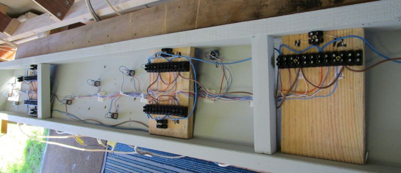
And the mass of wires for just 4 of the 12 switches:

'Petermac
Posted
Full Member
How are model railway items not considered essential?
Posted

Full Member
Peter, your panel is looking very neat. I am proposing to use tagstrip as a connecting method as I am told that the resistance introducted by the "chocboxes" is much higher. I guess it depends on ones ability to solder and assumes a vast store of heat-shrink protector!
Like others, I look forward to seeing the completed panel working.
Barry
Shed dweller, Softie Southerner and Meglomaniac
Posted
Full Member
Operation is going to be very much by trial and error and I have absolutely no doubt that I'll need to reverse some of the connections ………………….
'Petermac
1 guest and 0 members have just viewed this.