00 Gauge - Maxmill Junction
Posted
Full Member
Petermac's Railway
Got it Pete, your putting your layout on top of a workbench. :doublethumb :doublethumbSeriously I think your concept is great, nothing like making things easy and comfortable.
It ceases to be a hobby when things become uncomfortable.
 Last edit: by AUSSIETRAINS
John.

Posted

Full Member
I suspect there would be almost as much work involved making drawers or sliders etc. Nigel. Also, it might be worth mentioning that most of the sub frame was salvaged from the previous Maxmill so, apart from a few minor alterations, it was already "in stock".Why not make them on sliders or drawer runners? Then you can pull it out. Or make the top boards on hinges so you can prop them up. You will need flexible wiring for the droppers. Great idea. Putting the wiring on the underneath of the top board is actually not sensible if you think about it. I may borrow the idea even though my next layout is around 46" high.
Nigel
Not sure what you mean about having the top boards hinged - surely that would mean each board would effectively become a "lift-up". I have enough trouble ensuring the rails line up on 1 lift-up, never mind having more than absolutely necessary !!!
'Petermac
Posted
Full Member
You're right Matt - the piece of timber is just there to illustrate the idea. The actual electrics will be further back out of harms way.Peter I take it the piece of wood we see sitting flat.. In front of the riser is NOT the piece that will have electrics on ?
Will the electrics be on a plywood base behind that piece ?. . . My concern is if the electrics WERE on that front plank they would be vulnerable as it would be a convenient dumping place for tools, biscuits, cups of tea etc. But if you were to turn that front piece into an L shaped shelf, and leave it loose, with the electrics behind on their own shelf , It would protect the electrics, give you somewhere for your cuppa and be easily moved if you need to do some electrickery
:thumbs liking the idea though !
Cheers
Matt
I like the idea of biscuits and cups of tea - must tell Liz that one ………………………… :thumbs
'Petermac
Posted

Full Member
Nigel
©Nigel C. Phillips
Posted
Full Member
That's easy to answer Nigel - simply because it's an absolute dream to solder to……………..Neat idea. Why the copper tape?
Nigel
I stick 2 bands to whatever surface is to hand (it's self-adhesive) - one for "black" and one for "red". Each band is connected to the appropriate bus via 1.5mm stranded droppers and the smaller track droppers are then soldered to the copper tape. No stripping of bus insulation, no wrapping of wire around thicker wire, no difficulty heating a large diameter bus sufficiently to accept a good solder joint - or rather, I only have to do that once on each section. I do now have a gas powered iron so that may well be easier than with an electric iron, which I always found quite difficult and time consuming ………..
I have no idea what the maximum load of the copper tape is but on Maxmill I, I had no problems. The track droppers are soldered to the tape every few millimetres and it literally takes no more than a second to achieve a good joint.
'Petermac
Posted

Full Member
Thought you were back in the 60's then Peter[user=1632]BCDR[/user] wrote:and it literally takes no more than a second to achieve a good joint.Neat idea. Why the copper tape?
Nigel

Phil
Posted
Full Member
Innocently, Mum replied that a piece of beef would go down a treat. I'm sure they still feast on that occasion ………………..
'Petermac
Posted
Full Member
Phil
Posted

Full Member
Staying on the thread Kevin.
Posted
Full Member
'Petermac
Posted
Full Member
Nigel
©Nigel C. Phillips
Posted
Full Member
I wonder if Intel will offer me a job …………………….. :hmm
'Petermac
Posted
Full Member
Posted
Full Member
No Peter. Liz already employs you full time!!
:thumbs
'Petermac
Posted
Full Member
Staying on the thread Kevin.
Posted
Full Member
Today, I made a temporary lift up across the doorway to try out the lie of the tracks …………..
The result is that my planned 36 inch radius curve won't fit !!! I ought to have realised that. The unit is only 2.3m wide - a 3ft radius curve would need 6ft to create a semi-circle leaving only a few inches spare at the edges.
I think the best solution is to tighten the whole curve up slightly rather than just tightening the entry and exit areas. I'll probably end up with around 30" radius on the inner track.
Now, some advice please.
The plan in the storage/fiddle yard is to have 3 "up" roads and 3 "down" roads with 1 of each, the centre one, being the through routes.
The question is, do I use a 3 way point or 1 left and 1 right to access the adjacent storage roads ? If I opt for a 3 way, is there enough space between the throw ties to fit the necessary 2 Tortoise motors ? The 3 way point would save about 8 or 10 linear inches. Looks are not critical becase it's not on a scenic part of the layout.
'Petermac
Posted

Full Member
You can operate three ways with tortoises…..I have done so…..the tortoises have to be mounted back to back if you follow me?
However in such a critical area I would not recommend them. I have always found them somewhat unreliable and finally took both out…..they are ok as space savers in a little used yard but I would not use them on critical through routes.
I cant remember the radius of Code 100 curved points but they might be a possibility to start the ladder for one or both tracks. l use them on the entrance to my storage yard entry ladder.
Best wishes
John
Ps I do like your “ shelf†for wiring……..that plus copper tape……brilliant I just wish you had mentioned it 12 years ago!
Posted
Full Member
I had originally planned to use curved points but ideally, I'd like to keep all the points at the door end on the one large board in the earlier photos rather than on the corner board. It looks as if the curves will be finished by the time I hit that board and I'll have a straight run into the ladder.
Having just written the above, I wonder why I want to keep all the points on that board …………….. :hmm I'm sure there must have been a reason to want to keep them all together but it escapes me just now …………………………….. :???:
I'll have a re-think tomorrow when I can check possibilities using templates.
'Petermac
Posted
Full Member
I wanted to see what I could do with curved points but alas, their radius is far too big - the outer on a curved point is 60" - twice what I had hoped would fit but won't !!
Here's the lift-up board temporarily in place although I think I've cut it too fine - might have to make another allowing myself more room …………………. Obviously there is still a new panel to be made and fitted top left.

Two Tracksetta templates on the route of the inner line showing the difference between 3ft (green) and 2ft radius (red). You can see the 3ft radius would only just stay on the board - and it's the inner track ! The 2ft is much better although it still needs to end up closer to the inner edge of the board. I don't think any modern stock would have difficulty negotiating a 2ft radius curve ………….. :hmm :
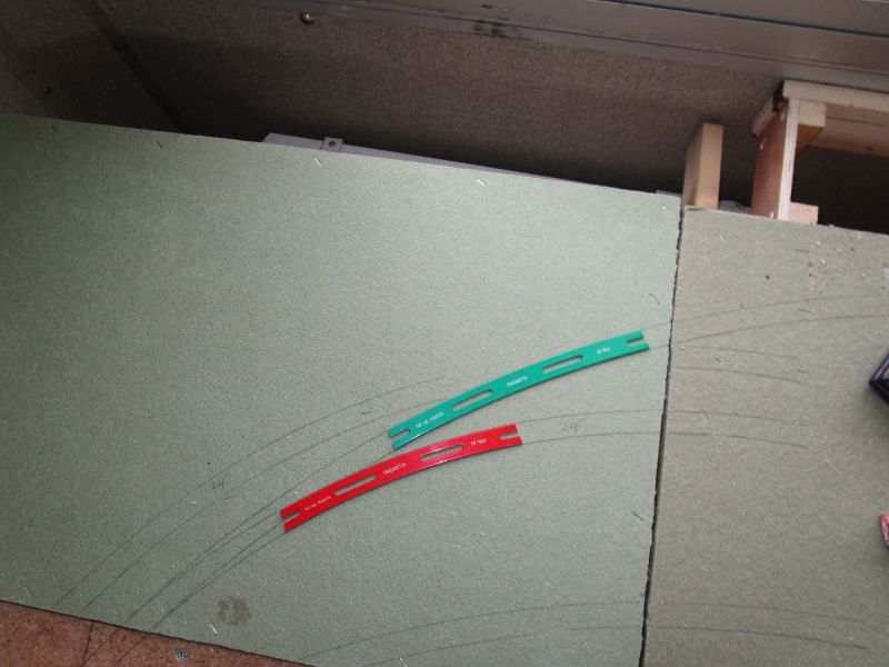
This length of track, roughly placed to see what it looks like, is 2ft radius :

Using medium left and right hand points, as opposed to a 3 way, this is how the ladder might look :
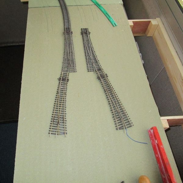
Any thoughts/comments anyone ?
'Petermac
Posted
Full Member
Assuming you have a similar set up at the other end how much storage space will you end up with? I guess you could use the two inner roads for storage and the shortest outer road as the through route?
Cheers
John
1 guest and 0 members have just viewed this.