00 Gauge - Maxmill Junction
Posted

Full Member
Petermac's Railway
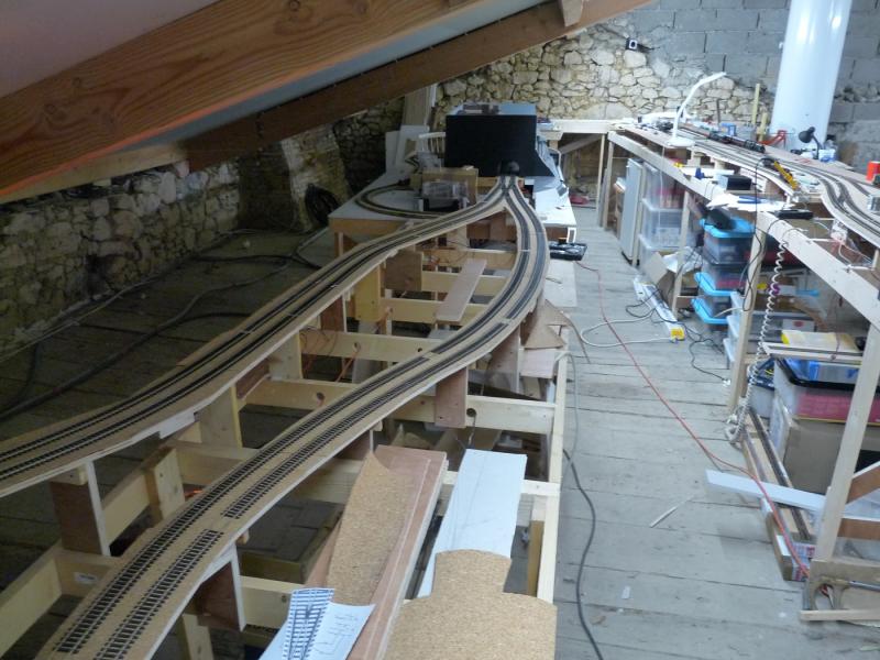
I've done a bit more track laying and planning since the last update.This shot shows the, now completed, "Maxmill Junction", where the branch to the terminus station (down the centre of the room and on the left in this shot) leaves the lower circuit to climb the 1 in 80 (ish:roll:) gradient of "Maxmill Bank" (the twin right hand tracks). The low level circuit (the left hand tracks) will ultimately form a lower level circuit around the outside of the available space and incorporate a curved through station and the main storage roads.
The end of the tube module (Chocolate Pudding Lane) can be seen bottom right above the twin railway tracks.

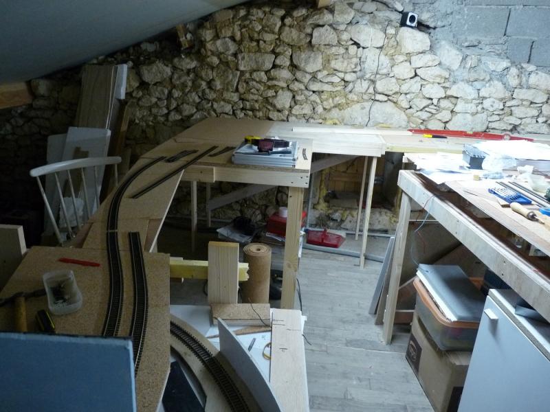
This is the same place but looking the other way. The terminus station is on the right. The curved through station will be tight up against the random stone wall at the far end. "Pudding Lane" tube module is the black structure under the "mind your head" timber beam.
This is the site of the curved station. The narrow duck-under where the white chair is on the left is for easy(er) access to the back of the layout. The idea is for the station to take 6 or 7 coach Pullman trains on a 5ft radius curved platform but I think that may be slightly wishful thinking …………..
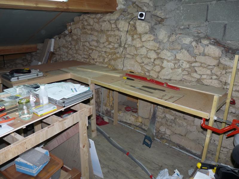
The baseboards for the curved station being fitted. The "sonar" device on the wall is supposed to deter rodents in the winter. We do have 3 cats but they're far too fat and too keen on lying in front of the fire watching TV. On the left of the shot is the end of the central "tongue" with the terminus station. There is room to walk between the boards but you can't hold a dance in there …………
This is the start of the storage roads. Two "through mains" down the middle with 3 roads on either side. The shortest storage road will be over 6ft long so there should be plenty of space. There will also be a kick-back siding top left accessed via a double slip so shunting can take place without blocking the main lines.

And that's just about as far as I've got. I've been soldering droppers and am currently awaiting deliveries of materials so that I can fit some of the Tortoise motors.
You'll note everything is very tidy - I do like a tidy workplace …………:shock::shock::shock:

'Petermac

Posted

Legacy Member
Peter we never expected anything lessYou'll note everything is very tidy - I do like a tidy workplace …………:shock::shock::shock:
Bozzy(never known to pass a pub)
Posted
Full Member
You'll note everything is very tidy - I do like a tidy workplace …………:shock::shock::shock:
That is very tidy compared to my railway room:shock::shock:. The progress looks good.
I can't actually get around it at the moment. It is full of boxes whcih remain unpacked as of 2yrs
 :roll:.
This site has spurred me on to design a new layout though so some progress may be made soon-ish. But don't hold your breath:roll:.
Simon
Posted
Inactive Member
I must say I am very impressed by your open plan baseboards and intricate woodwork. Beats my dining room table top approach by a mile.
Talking of cat,s and rodents my boss likes to bring in the odd mouse so we can play together! At least I think that,s her feline plan. The ancient Romans would have approved her arena approach.
regards,
Derek
Posted
Full Member
I haven't had the time (or the inclination) to do much modelling this spring. "Catchy" weather has made it a very difficult time for us poor ex-Pats down here but I have recently been fitting some Tortoise point motors controlled by a Lenz LS150 accessory decoder.
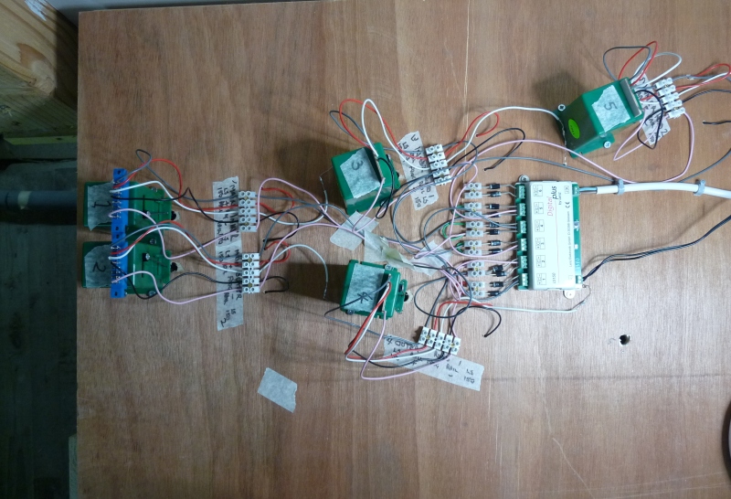
There are 6 motors in this location controlling the entrance/exit to my storage roads. All 6 motors are mounted on a "lift out" panel so that I could work on them from above. The board is just flipped upside down and back again depending on what I'm doing. Once everything is fitted and tested, it will be screwed down.
I had intended to keep all my wiring neat but seemed to run out of space with this "DCC is only 2 wires thing" !!! :roll:. I have a book with all the colour codes noted so if anything goes wrong, I'll know how to sort it. So, if anything goes wrong, I'll know how to sort it, so, if anything goes wrong, I'll know how to sort it, so if …………………………………………..:lol::lol:
Here's the underside of the panel with 5 of the motors fitted, wired and tested. The hole lower right is where the 6th motor goes but I pinched it's point to use elsewhere so need to buy another one :???::
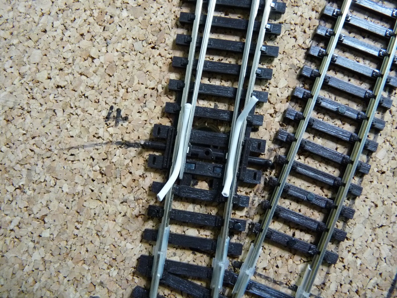
I did come up with what I thought was a neat idea for centering the Peco points before fitting the motors. My dropper wire is nearly a perfect fit to center the points. A piece on each side of the closure rails, held in place with masking tape whilst the motor control wire was fed through the hole in the tie bar whilst piercing the masking tape as it went through. It can be used if working under the baseboard too although I don't look forward to fitting motors from underneath ………….:shock::shock:
Here's what it looks like:
'Petermac
Posted

Full Member
Good to see progress.
Posted
Full Member
are you using dcc if so do you modify the peco points for the dcc?
Posted
Full Member
Be my guest Jimmy re the centering method - it does work and it is very simple !!that is a really good idea to center the points i will steal that idea.
are you using dcc if so do you modify the peco points for the dcc?
The layout is DCC and yes, I do modify the points - they're Electro frog and DCC controlled via the Lenz accessory decoder.
I remove the little wire link between the frog rails and main rails underneath. I add a link between the outer and closure rails using the wire that then becomes my dropper to the DCC bus. I think this method is recommended by Peco on their instruction leaflet enclosed with the points.
I'll take some photos next time I do one so those who haven't done it before can see how easy it is.
This of course, is only for "Electrofrog" points ………………….:roll:
'Petermac
Posted
Full Member
That first picture will eventually make a very good coloured sweater if the electrics don't work,……………………….
In which case, perhaps I should re-name it "Brandreth Junction" - problem is, it's all in short lengths ………….:cheers
'Petermac
Posted

Site staff
You look to be progressing well :thumbs
I read through from the beginning yesterday, then got side-tracked into Trams which took me into yesterday evening.
I did stick one piece of plastic to a piece of wood on my layout though!
Another large layout for me to be envious of …………….. ho, hum.
Ed
(P.S. Please tell me you tidied up especially to take the pictures)
Posted
Full Member
Been there, done that and got 2 tee shirts Ed ………………that's why this layout has been 300 years in the making and I still can't drive a train around it. :cheers:cheers………………………………………………..then got side-tracked into Trams which took me into yesterday evening.
I did stick one piece of plastic to a piece of wood on my layout though!
……………………………………..
(P.S. Please tell me you tidied up especially to take the pictures)
I did tidy up for the latest couple of photos - I didn't want the whole world seeing my dirty washing. As some of the earlier photos will confirm, I work in a total mess but I usually know which lump of timber my screwdriver is hiding under ……"usually" being the operative word.;-)
'Petermac
Posted

Banned
…….that's why this layout has been 300 years in the making and I still can't drive a train around it. :cheers:cheers
Does that mean we will see Romans and horse drawn carts on the layout…?? :lol::lol:
On another note, those baseboards and sub frames do look good ! :thumbs
Cheers, Gary.
Posted
Full Member
It's all a bit like pushing the track out in the early days of the railways. You have to build the bridges before you can cross the river ……..:roll::roll:
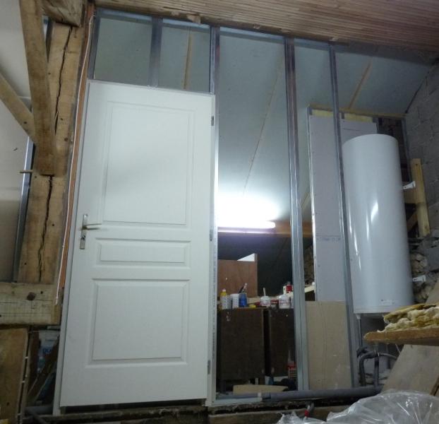
I had around 2 metres of stud walling to finish in a very awkward corner around a hot water cylinder, half of which was to include a doorway. Here's the "skeleton" with the door in place awaiting the plasterboard :
From the inside, plasterboard now in place but the joints still to seal. As it's only an attic "space", I'm not doing much in the way of "decoration" up there beyond a bit of tarting up on that bad corner :oops::oops::
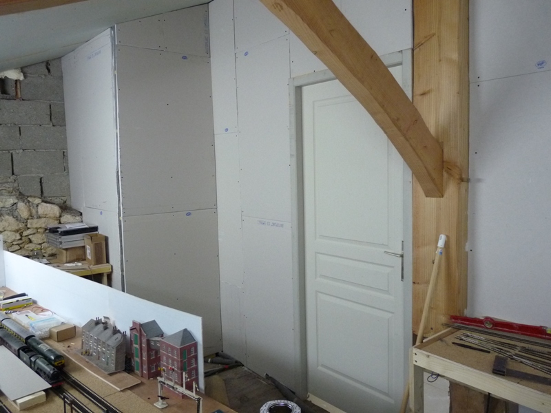
The "missing link" before the circuit can be completed, is the section between the baseboard where the level is and that you can see just above the "island unit" with the light blue backdrop - only about 2 metres but I'll have to incorporate a lift-up flap or some other means of allowing access through the door from the rest of the attic (which also houses the access to the attic from the house …..)
'Petermac
Posted
Full Member
I have stumbled over your layout having seen the wonderful shots on the Scalescenes station roof thread. I had somehow missed developments. I have to say it does look superb, and until I saw these recent pictures I had no idea that the layout was so extensive, or indeed advanced in its development. I have been reading all your projects with interest but now I can see the whole thing coming together. It looks impressive and I look forward to more.
Bob
Posted
Full Member
It's a slow job - I don't seem to get much time for modelling - however hard I try, something "more important" (according to the Memsahib) always seems to crop up !!!
'Petermac
Posted
Full Member
'Petermac
Posted
Full Member
This time, we head off on the lower level main line circuit (the previous video went off to the right up "Maxmill Bank" to the "Town" station.) Still no scenery, just the bare tracks but it does give an idea of the layout in full.
The truck mounted camera (a Hero 3) clobbered a waiting blood and custard train near the end - sorry about that - and is too wide to go through the tunnel under "Chocolate Pudding Lane" tube module so stops there.
'Petermac
Posted
Inactive Member
Even under the domestic whip you are making great progress.
These large railway builds are not for the impatient types!
Thanks for shareing.
Derek.
Posted

Full Member
Loved the sound ……you must stop tempting me…………………was that the Pannier?
I like the idea of a wagon mounted camera…….when you have time could you post a few photos and details……I am definitely tempted here!
Cheers
Posted
Full Member
It's one of those clever sports cameras. I usually wear it when I'm ski jumping or sky diving …………………..:roll::roll::roll::roll::roll:
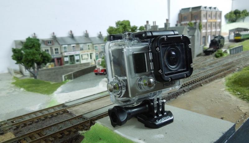
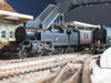
I took it out of the case and sat it on a truck chassis. It's too wide and, to get it balanced, it's not sitting centrally on the truck. Cornering at speed is certainly a no-no !! :lol::lol: I've also recently acquired a key-ring "spy camera" which is much happier on a "OO" Gauge wagon and passes through Chocolate Pudding Lane tunnel with ease. On the down side, it needs far more light than the Hero and resolution is not as good by a long way. I'll check to see if I've uploaded a video taken with that for comparison.
Her's the "Hero" mounted on the truck chassis:
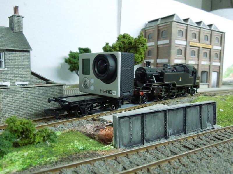
'Petermac
1 guest and 0 members have just viewed this.