00 Gauge - Maxmill Junction
Posted

Full Member
Petermac's Railway
Thanks for that link Dave. It seems there will be something for me to see at both York and Shildon whilst I'm over. :thumbs
'Petermac

Posted

Full Member
I am guessing you are now committed to insulfrog points. Have you now determined the operating method? Is the motor already in place for the fixed Y?
:cheers
Posted
Full Member
I'm not at all committed to Insulfrog points - in fact, quite the reverse …………from now on !!! The "Y"'s you see there are "existing stock" as are most of those currently in place. Future purchases will be Electrofrog.
There are no point motors in place yet but holes are drilled through the baseboards to take them (except where I forgot initially :oops:).
Regarding operating, I'm still leaning towards throwing switches on a facsimilie track plan in the "signal box". I'll have to get my brain around all the wiring for that.
I'd like LED's to show the route set as I throw the switches. I'll also have "section switches" on the plan, similarly showing what's live and what isn't. This is so that I can, when necessary, and in the short term, run DC locos. I do plan to chip them all eventually (or sell those I can't) but my bank manager (Liz) keeps telling me to learn to walk before I try running. Chips (the type I need) are fairly expensive in bulk ………. ………..
The "Great Divide" between Lowry country and Constable country will be along that concrete block wall - probably in the form of the "Standedge" or "Summit" Tunnel under the high moorland.
I remember seeing a US outline layout where he'd made "pictures" all with totally different themes - a bit like our YMR module set-up. Each "theme" was viewed through a picture frame facia and, to ensure you didn't get confused, only the scene he wanted you to look at was lit - the rest being in near total darkness. It was extremely effective and gave the modeller the oportunity to model a whole range of diverse scenes without the need to link them visually.
'Petermac
Posted

Full Member
I see you are making good progress with the wood and track work. Your lamp head does look a spaceship - another theme maybe :lol:
Posted
Full Member
Hi Peter,
I see you are making good progress with the wood and track work. Your lamp head does look a spaceship - another theme maybe :lol:

The transport system, including the tube and trams could possibly serve a developing rocket site ……………….or that part of the layout could be a diorama for "Horsham Common" and the martian landings in "War of the Worlds" ………..maybe I should paint the ceiling green :roll::lol::lol::lol:
'Petermac
Posted
Full Member
:thumbsI phrased the question delicately just in case! I dont believe you will regret the decision for one moment. Wiring the points for polarity switching is a breeze with the new Peco point……no more horrible gashes with a dremel. So with LED indication you will need double switches…………..what type of motor/switch have you opted for?I'm not at all committed to Insulfrog points - in fact, quite the reverse …………from now on !!! The "Y"'s you see there are "existing stock" as are most of those currently in place. Future purchases will be Electrofrog. There are no point motors in place yet but holes are drilled through the baseboards to take them (except where I forgot initially :oops:).
:thumbsI think with a layout of your size you are absolutely right to go for some form of central control. I imagine you will go for a separate Power Bus for the point motors…………and will you need another one for the LEDs? There will be lots of wires but it shouldnt be too complicated particularly if you can get hold of old multicoloured telephone wire or similarRegarding operating, I'm still leaning towards throwing switches on a facsimilie track plan in the "signal box". I'll have to get my brain around all the wiring for that.
I'll also have "section switches" on the plan, similarly showing what's live and what isn't. This is so that I can, when necessary, and in the short term, run DC locos. I do plan to chip them all eventually (or sell those I can't) but my bank manager (Liz) keeps telling me to learn to walk before I try running. Chips (the type I need) are fairly expensive in bulk ………. ………..
I am less certain about this:hmm
I am not sure about the actual technicalities of dual running……switching between DC and AC……. but the concept does seem fraught with both complexity and potential danger…….DCC locos not set up properly for DC runnning….pouff!:twisted:
I do agree about the cost……it took me 5 years to finish chipping…..in fact I still have to do the last one (a split chassis of course)…………I tended to focus on the scenery which takes time but not much money and initially chip just a few locos to operate.
I think that is a great solution….I am sure it will look spectacular :thumbsThe "Great Divide" between Lowry country and Constable country will be along that concrete block wall - probably in the form of the "Standedge" or "Summit" Tunnel under the high moorland.
:cheers:cheers
Posted
Full Member
What do you mean by "double switches" John ? Do you mean 1 switch for the point and a second for the route ? I'd hoped it would be possible to wire them so that the route was shown when the point was set but that may be wishful thinking ……..:roll::roll:
I'm planning to use tortoise motors although I do have a few old Seep/Peco/H&M type motors floating around which I may make use of.
…………………I imagine you will go for a separate Power Bus for the point motors…………and will you need another one for the LEDs? There will be lots of wires but it shouldnt be too complicated particularly if you can get hold of old multicoloured telephone wire or similar
The point motors will have their own bus but again, I'd hoped setting those would also light rthe appropriate LED's :???: I do have a fair bit of telephone and alarm cable in the garage but wondered about the capacity over long lengths.
I am not sure about the actual technicalities of dual running……switching between DC and AC……. but the concept does seem fraught with both complexity and potential danger…….DCC locos not set up properly for DC runnning….pouff!:twisted:
This part will be the pain - at least until I've either chipped or sold the DC locos. I did have a slight "spree" on an auction site a while back, hence the DC locos ………..
 When running on DC, I'll remove ALL DCC locos and, once the session is over, swap them again.
 Even as I write this, I do wonder if I'm creating a lot of work (and expense) for section switches in the short term, and might be better off putting the effort and cash towards chipping those I'd like to run ……………………….:roll::roll::roll:
'Petermac
Posted
Full Member
:doublethumb Tortoises are to my mind absolutely the right choice…………….I just wish I had converted to them sooner. You get 8 contacts on a Tortoise…….2 to throw the point and 2 switches each with 3 contacts……..so you can throw the point, change the polarity on the frog with one switch and power the route LEDs with the other. The cost is very close to the combined cost of a peco motor and double (DPDT ???? or similar:oops:) switch and far more reliableWhat do you mean by "double switches" John ? Do you mean 1 switch for the point and a second for the route ? I'd hoped it would be possible to wire them so that the route was shown when the point was set but that may be wishful thinking ……..:roll::roll: I'm planning to use tortoise motors
.although I do have a few old Seep/Peco/H&M type motors floating around which I may make use of
Based on my own sad experience (I have to spend the afternoon yet again crouched under the baseboard trying to fix a peco switch for a crucial point at the entry to the storage yard)……… I would confine their use to insulfrog points in non strategic areas and ideally have them surface mounted.
I think that should work…..but I am no expert. I have used that type of wire over fairly long distances 15' or so without any problems for individual point switching…………..I wire the common bus using a slightly heavier gauge and tap off it……there is probably a better term for that!The point motors will have their own bus but again, I'd hoped setting those would also light rthe appropriate LED's :???: I do have a fair bit of telephone and alarm cable in the garage but wondered about the capacity over long lengths.
I know what I would do………………..:pedalEven as I write this, I do wonder if I'm creating a lot of work (and expense) for section switches in the short term, and might be better off putting the effort and cash towards chipping those I'd like to run ……………………….:roll::roll::roll:
:cheers
Posted
Full Member
The Seeps (or whatever they are) will be strategically placed so that, at the flick of a switch, they'll instantly flatten any mosquito brave enough to settle on my control panel or wherever and Tortoises will be used throughout.
I'll make use of the telephone/alarm cable somewhere within the route/point/LED circuitry. I've probably got 300 metres of the stuff looking for a use.
My DC locos will be temporarily "laid up" until I get around to chipping them (including the DCC Ready Std.Class 4 that only arrived on Saturday from Cornwall …). The layout will be totally DCC. Having "played" a bit last evening with a couple of DC locos (the 4-6-2's to check curves and grades) on a DCC layout (admittedly without section switches), I know which is more fun ……………:thumbs:thumbs
Thanks for the kick in the right direction John. :cheers
'Petermac
Posted
Full Member
Thanks for the kick in the right direction John. :cheers
No point in you discovering square wheels dont work as well! Glad you found it useful:cheers
Posted
Full Member
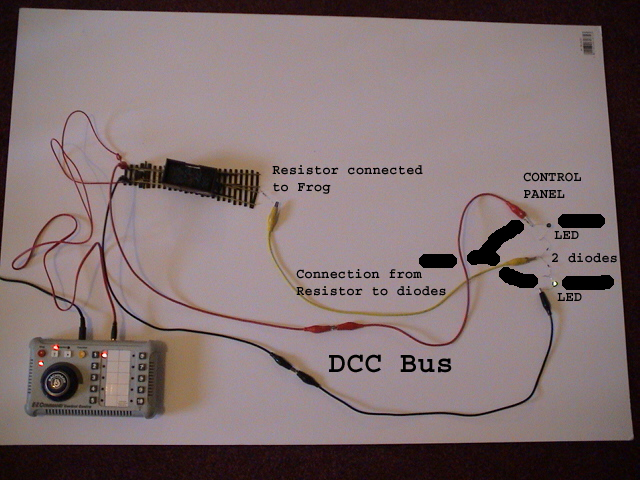
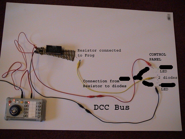
One resistor at each point with one end connected to the frog. One wire from the other end of the resistor to the control panel. Two LEDs on the control panel showing each direction of the point, with one end connected to the DCC bus as shown. Two diodes each between the other side of each LED and the single wire from the frog. These diodes are just to protect the LEDs from the AC waveform of the DCC bus. It doesn't matter which way round the LEDs are connected.
When the frog is connected by the point motor switch to the red side of the DCC bus, the LED connected to the black side will light up. When the frog is connected to the black side of the DCC bus, the LED connected to the red side will light up.
Very cheap, and very effective, and does not drain very much from the DCC bus.
Posted
Full Member
As you probably know, electronics is not my thing but, once I've digested and understood the circuits, it will come to me ……..:???:
Added to that, I've just this minute walked in from a neighbours where we'd opened a rather nice bottle of so I'm not totally complus-mentus at this moment………………………………………………………..:cheers:cheers
'Petermac
Posted

Full Member
Busy building a new show layout …..
www.westcoastminiatures.com
www.westcoastminiatures.com
Posted
Full Member
Come on, don't leave us in suspense. What was the nice bottle of …? Must have been really good. :lol:Added to that, I've just this minute walked in from a neighbours where we'd opened a rather nice bottle of so I'm not totally complus-mentus at this moment………………………………………………………..:cheers:cheers
Posted
Full Member
Moving right along………Peter is using Tortoises to power his points so wouldnt he use one of the tortoise switches for the switchboard LEDs?
Posted

Site staff
Yes, a good point John - Tortoise/Cobalt for both frog switching & panel indication & if using LED in series with Tortoise operating wiring, in-built switches are not needed - see attached on Page 2
Moving right along………Peter is using Tortoises to power his points so wouldnt he use one of the tortoise switches for the switchboard LEDs?
Ron
NCE DCC ; 00 scale UK outline.
NCE DCC ; 00 scale UK outline.
Posted

Full Member
Sol beat me to it - (sort of) - but I unless you've already purchased the Tortoise motors I would strongly recommend that you consider the Cobalt motors from DCC Concepts. http://www.dccconcepts.com/index_files/Cobalt_turnout_motor.htm They are, IMHO, much neater than the tortoise motors and there's a price advantage to boot.
Regards,
Trevor
Trevor
Posted

Inactive Member
Your comment has my brain cramping. I read somewhere that the Cobalts have struck a problem.
I can't remember the details (oldtimers). :oops: . . . but it will come to me - eventually. :shock:
Max
Port Elderley
Port Elderley
Posted
Full Member
The RLW that did the damage was a bottle (or two) of 2009 (a good year) of Chateau Brillette Bordeaux red - and very good it was too !!!
I'm slightly more able to see what's going on in your diagram Geoff but, as John said, I had understood that there would be a spare switch available on the Tortoises which I could use for the route LED's. Is this correct …………..?
Trevor, I too had heard that Cobalt had encountered some (reliability ?) problems - I'm not sure if they've resolved them but, whilst I haven't yet purchased the motors (too many other demands on resources at present), because I haven't heard of any problems with the Tortoise, that's the one I'm going for.
I'm not "into" electronics so reliability from a tried and tested unit it vitally important to me. As with computers, if I switch it on and it works, that's great, if it doesn't, I'm totally stumped …………..
It's just the way my brain works (if at all !!) - I have to be able to "see" something, not "imagine" it. I've said before, I'm mechanically minded, not electrically …………:oops::oops:My current priority with the layout is to complete the lower level "circuit" - at least with a single track - so that I can let locos run around to bed them in and also, to test decoder adjustments properly by allowing them to attain their full speed. At present, it's a matter of running them from end to end - albeit a run of around 50ft….
To that end, I'm awaiting delivery of the long crossing for the "Junction" and have around 40ft of further baseboards to construct to close the circle.
This hobby does tend to eat up money - I'm now thinking I need one of those extremely expensive track cleaning wagons - I'm getting a little tired of "leaves on the rails" bringing things to a halt during the dusty "building phase" of Maxmill Junction :hmm.
'Petermac
Posted
Full Member
There was, apparently, a bad batch of Cobalts about a year ago but AFAIK that was fully resolved at the time.
This is a link to the topic on another forum which may be what you are referring to. http://www.modelrailforum.com/forums/index.php?s=51216c750e9b590b6ee81daad9f082ec&showtopic=19342
I would not normally post a link to another forum but, in this case, I hope it can be permitted as it seems the best way to resolve this particular issue.
Regards,
Trevor
Trevor
1 guest and 0 members have just viewed this.