00 Gauge - Maxmill Junction
Posted

Full Member
Petermac's Railway
[user=269]MaxSouthOz[/user] wrote:Looking great, Peter. :thumbs
Track code changes can be made using metal joiners. I know, heresy - but needs must. Flatten one side of a Code 100, slip it on to the Code 100 track and then slip it under the Code 83 and solder it in place.
….oh, Max, you really are the Ned Kelly of Railway Modelling! A man of Peter's diameter, sorry, calibre, will want these…..Peco SL 113, and at about £6 for a pack of 4 are as nothing to a man of his means……
They are even sold at outlets in third-world regions, see
http://www.kernowmodelrailcentre.com/product/37978/SL113_Peco_Transition_Track_for_joining_Code_75_to_Code_100
Tee-hee!
Must go, it's raining lightly here and I want to go and run around in it………..starkers!
Doug
 Last edit: by Chubber
'You may share the labours of the great, but you will not share the spoil…' Aesop's Fables
"Beer is proof that God loves us and wants us to be happy" - Benjamin Franklin
In the land of the slap-dash and implausible, mediocrity is king
"Beer is proof that God loves us and wants us to be happy" - Benjamin Franklin
In the land of the slap-dash and implausible, mediocrity is king

Posted

Site staff
I used Max's method when I had to connect code 100 Peco to Code 83 Tillig turnouts. I found the Peco Code 83 & 75 use the same size joiners ( two different coloured packs though) & lightly file the end of the Code 83 to match the code 75.
Did you get wet from the rain?
Ron
NCE DCC ; 00 scale UK outline.
NCE DCC ; 00 scale UK outline.
Posted
Full Member
Doug
'You may share the labours of the great, but you will not share the spoil…' Aesop's Fables
"Beer is proof that God loves us and wants us to be happy" - Benjamin Franklin
In the land of the slap-dash and implausible, mediocrity is king
"Beer is proof that God loves us and wants us to be happy" - Benjamin Franklin
In the land of the slap-dash and implausible, mediocrity is king
Posted
Site staff
In that case, yes, either transition track SL-113 or joiners SL112I remember, I used Peco 75 to build the t'table, and if I read correctly, Peter is using Peco 100? Should be O.K.?
Doug
Ron
NCE DCC ; 00 scale UK outline.
NCE DCC ; 00 scale UK outline.
Posted

Full Member
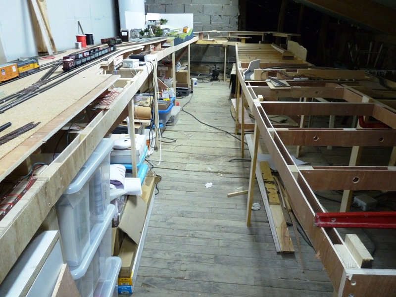
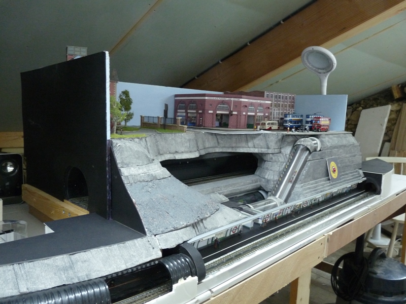
This is what it looks like tonight:
The high level "Maxmill Town" terminus is on the left. The higher curved board at the far end will fall to join the lower level somewhere around the right forground where the level is. On the right, the white foamboard sticking up is the first loop of Chocolate Pudding Lane.
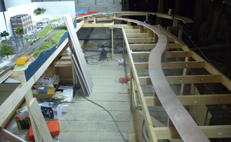
Looking the other way - the site of Chocolate Pudding Lane is clearer in this shot. The boards will continue aroud the far end then return along the wall on the right in this shot before completing the circuit roughly where the photgrapher is standing.
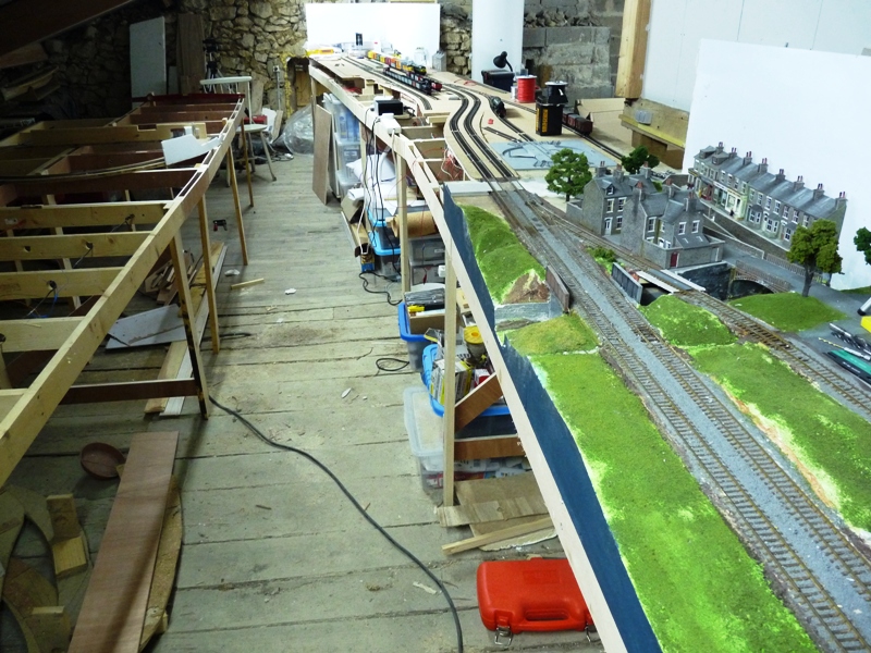
Excuse the mess - this is still a "building site" :cheers
'Petermac
Posted

Inactive Member
Max
Port Elderley
Port Elderley
Posted

Full Member
The baseboard construction looks very robust and well made……I have not seen that method before.
Those Metcalfe workers cottages do look the part, I rather wish I had used the grey option instead of red brick . I loved that little cameo back in July with the tree……promise of things to come!
It may be an optical illusion but it looks kind of narrow at the end……what will the radius be?
Kind Regards
Posted

Full Member
Posted
Full Member
The "main" section with the terminus is a high level spur surrounded, at a lower level, by the "circuit". The "under construction baseboards" you can see (where Chocolate Pudding Lane is) form one long side of the circuit and the other side will be up against the plasterboard walling which in turn, is around 3ft 6ins away from the spur. This side will just have storage roads - 3 in each direction some between 6 and 8ft long.
I really must do a track plan so you can see what's going on ………………:roll::roll:
'Petermac
Posted
Full Member
The station platforms on 48" radius will be a challenge though…….Scalescenes or? Is the intent still to have a Scalescene overall roof on the curve?:cheers
Posted
Full Member
There will be a continuous circuit at the lower level and a "junction" after the tube module up to the higher level where "Maxmill Town" is situated. If my tape measure is well made, I'll have a gradient of around 1 in 80. I had hoped to go for 1 in 90 by having the junction before the tube module rather than after it. That won't now be practical because of the need to access the gubbins behind the tube station which would end up hidden under the track bed for the gradient.
It's all a matter of being able to access the bits I need to. I'll have to crawl under the layout to get to the rear of Chocolate Pudding Lane. The electronic wizardry is all at the rear of the module and I'm very tight for headroom under that main roof beam you can see (actually, you can't see it in these last shots but it's big and it's hard and it is almost over the tube site !!!). Bump caps will be an essential. Ideally, I'd need to move all the electronics to under the tube module for easier access but, looking at Geoff's maze of wires, I think I'll just risk banging my head …………… On the other hand, all the actual relays etc. are very neatly built into a box so it may just be a case of using some extensions from all the multi-plugs. I'll see what Mr Electronics himself says …….
I had originally hoped to be able to walk around the back along the "stone" wall end but that's not going to be possible with the curved station there. Maybe I placed the spur a little too close to that stone wall …………:oops::oops::oops: I'll raise the baseboards after the tube rather than having the trackwork on risers to allow more clearance between the floor and underside of the boards. The curved station boards will all be solid top.
'Petermac
Posted
Full Member
Bob
Posted
Full Member
I reassembled Chocolotate Pudding Lane where it will sit on the layout. I did have huge problems getting the trains to run through the left hand tunnel but, with the help of diggers, blasting powder and a heavy hammer, all now works well.
This is where it sits in relation to the rest of the layout:
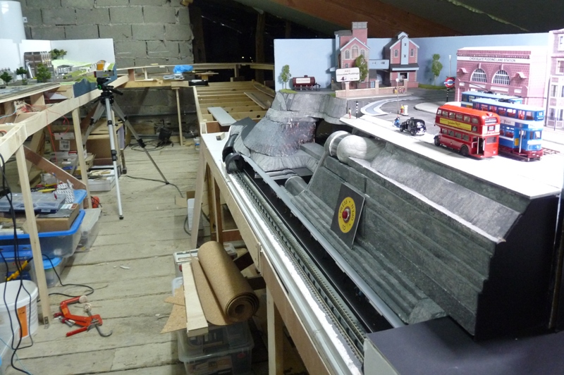
And this shows that troublesome main timber that interferes with my hairstyle whenever I need to access the controls for the tube module (That's a craft light you can see, not a Martian Fighting Machine from War of the Worlds !!!) :
Thoughts then turned to trams ………….
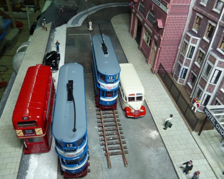
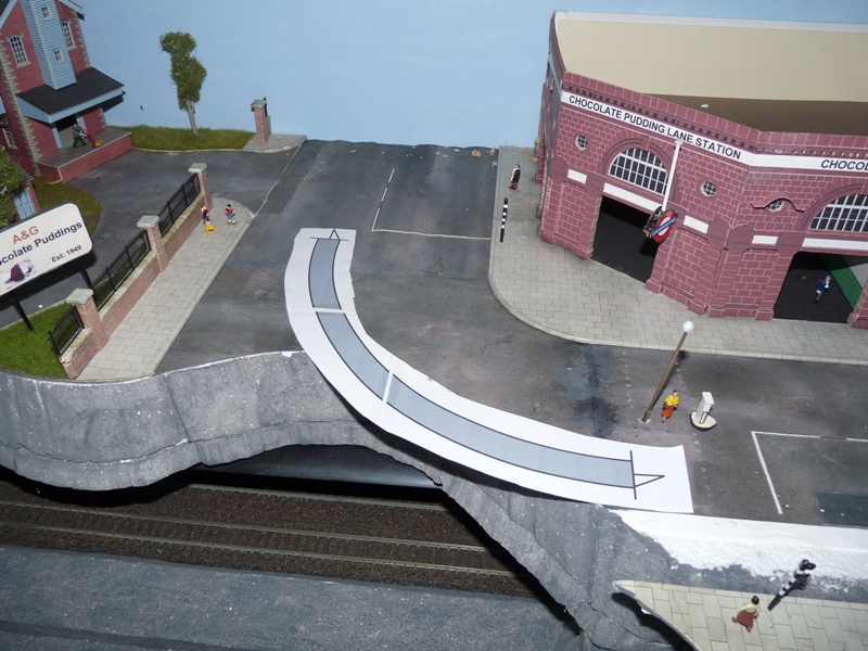
If I move the pavement forward, I have room for a doubled tram track in the centre of the road with space for vehicles either side:
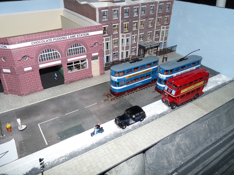
The "Keep Left" sign and lamp post will have to go:
Tram tracks can run much closer together than railway tracks so I can gain more space than shown in this shot:
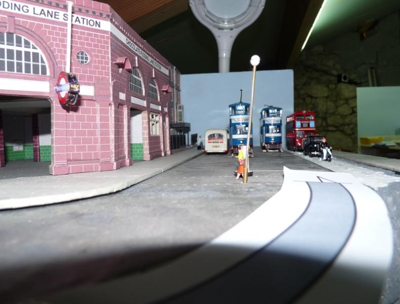
Turning the corner around the tube station will require a tight curve. This one is an "Anyrail" print of an 8" radius curve. My 4 wheel Leeds "Horsfields" should have no trouble negotiating such tight curves although I may have problems with the ex-London Feltham bogie trams. This was prototypical - when Leeds bought a batch from London, their routes were restricted to those with fairly generous curves. The tracks will then disappear behind the module and eventually, form a complete circuit taking in "Maxmill Junction" station:
'Petermac
Posted
Full Member
"Mind the Doors".
Posted
Full Member
I don't know yet whether to use Peco Code 75 flexitrack or to try the Proto 87 girder rails from the States -
http://www.proto87.com/easy-street-track-system.html
The advantage with the former is the depth. This would allow me to infill with some kind of plaster and score in the cobblestones.
The advantage with the latter is that it's more "prototypical" being "girder rail" plus it comes in pre-formed curves. However, it's not very deep so infilling with plaster might be a problem in that a thin coating would be quite brittle.
Either way, I'll have to "shim up" the buildings and pavements on some thin ply - a) to take the track pins, wiring and traction poles which have to be pretty rigid and b) to preserve the kerbs once the road deck is laid.
'Petermac
Posted
Legacy Member
reg
Posted
Full Member
Auhagen do some really nice sheets of cobbles that actually join together and are about 1.5mm thick.
http://www.auhagen-shop.de/product_info.php/info/p32838_1-cobblestone-single---br---Accessory-sheet---plastic.html
I have used some for a friends layout I'm helping him build and it is nice stuff.
Posted
Full Member
For UK, they will have to be the stone setts. Whilst they're available in pre-printed form or, by using a "Linka" type mould for casting, the problem with rigid sheets of any type, comes with getting a good fit on corners etc. Slow and tedius as it is, scoring seems to be the best way from what I've seen / heard.
'Petermac
Posted

Full Member
ps. MIND THE DOORS :Red Card
Busy building a new show layout …..
www.westcoastminiatures.com
www.westcoastminiatures.com
Posted
Full Member
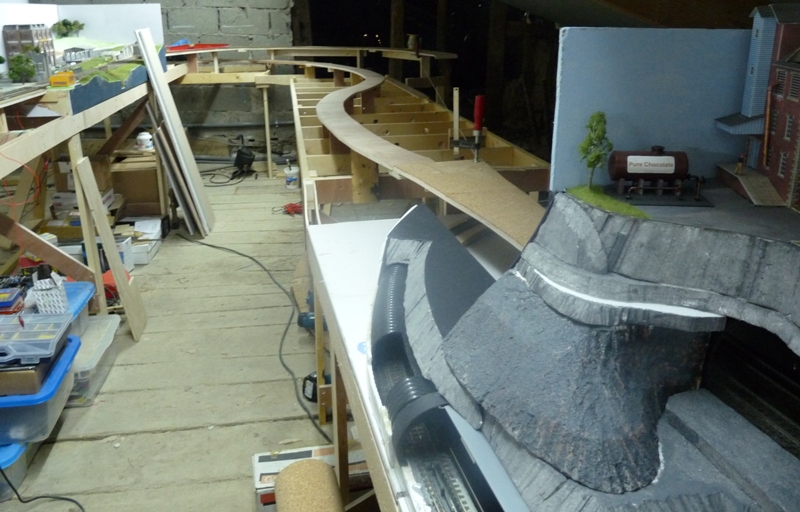
The "Town" terminus level will join the low level circuit at what is "Maxmill Junction" just after the tube module. The link line is the upper curve seen here and the gradient starts at the bit jutting out to the right of this shot (you can probably just about make out the string line). I need to drop around 2.5 cms and have a length of 320 cms to do it in. I'm happy with that.
This is what gives the layout it's name - the actual "Maxmill Junction". As trains exit the tube module (the black face seen here), they will either take the double tracks to the right which will form a complete circuit wrapping around the high level "Town" station, or take the tracks to the left which rise up to the "Town".
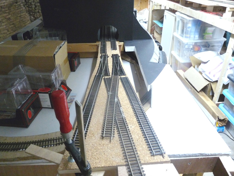
'Petermac
1 guest and 0 members have just viewed this.