00 Gauge - Maxmill Junction
Posted
#4310
(In Topic #572)

Full Member
Petermac's Railway
I did start a thread on the previous forum but, when it went down, all was lost (fortunately !!)Having studied comments on the forum, I've had to have a slight re-think !! As ever, time, cash and space just won't permit me to build the complete East Coast main line on my workmate !!
The basic station plan - all I've roughly planned up to now - will remain the same - twin tracks, bay platform and a couple of sidings incorporation goods shed, cattle dock and engine facilities with headshunt - the main difference is that the twin tracks will converge into single track once outside the platform area. My main line has now become a branch line !!
As for the name - I just don't have a clue. I had thought of "Dunnow Junction"; "Whishton Petesworth"; "Petesdream Magna" etc.etc.
Ideas would be gratefully received.
Petermac
'Petermac

Posted

Legacy Member
Posted
Guest user
Posted
Full Member
You can see the boards on the baseboard thread.
Petermac
'Petermac
Posted
Legacy Member
Posted
Full Member
I presume I just use copy - paste ?
I'll give it a bash.
Petermac
'Petermac
Posted
Full Member
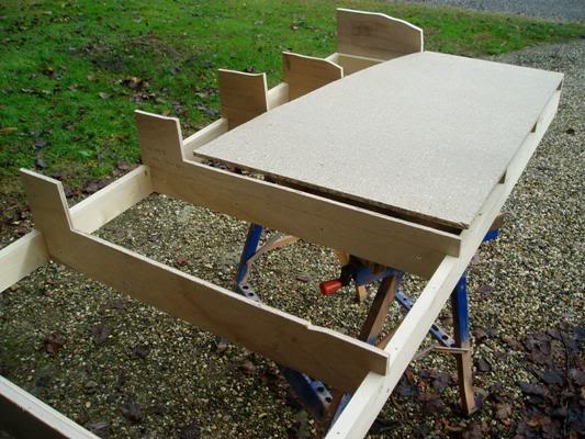
Basically, it's a sort of "open-top" with the trackbed being raised 35mm above the sub frame. The idea behind this is that (at some later stage) I want to run at 2 levels. I can therefore drop 1 track by 35mm whilst raising the other by the same amount giving my clearance in half the usual distance.
There will be 2 boards like this - each 5ft x 2ft 6" covering a station. The layout will extend into open countryside on each side - cuttings, tunnels and bridges spring to mind.
The sub frame (glued and screwed) is 70mm x 22mm, the risers are 10mm ply, the track bed is 10mm chipboard and the former at each end of the boards is 15mm ply for added strength at the board joints. As you can see, the 2nd piece of chipboard has yet to be cut and placed. The trackbed is screwed to the 10mm ply riser and should be self-supporting between the risers so that point motors etc. can be fixed/accessed below without too much difficulty.
Petermac
'Petermac
Posted
Full Member
What did I forget ? I'll have try to get photobucket to do as I think !!!!
Hope this works !!
Petermac
'Petermac
Posted
Full Member
Try again !!!!!!
Petermac
'Petermac
Posted
Legacy Member
Posted
Full Member
I've surely got a long way to go and a lot of learning to do but, with all the help on here, it'll gradually take shape.
Petermac
'Petermac
Posted
Legacy Member
Posted
Full Member
The result is, my plan won't fit where I wanted it to ! :oops: :oops:
As ultimately, I don't think space weill be a major problem (within reason), I've decided to extend the planned 10ft station section by a further 5ft board. This should allow me to get my "throat" as I want it without having to use either small radius points or too tight radius curves. If possible, I see flowing lines with gentle curves using no less that med. radius pointwork.
Back to the drawing board but not too bad - I've already thought about what to do with the extra space.
I'd do a track plan but just can't get to grips with the CAD freebies - the scale comes out completely wrong and, as my screen isn't 8ft wide - I can't see what happens to the end of the track off screen !!!!
Back soon.
Petermac
'Petermac
Posted
Legacy Member
Posted
Full Member
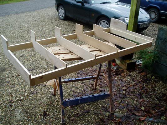
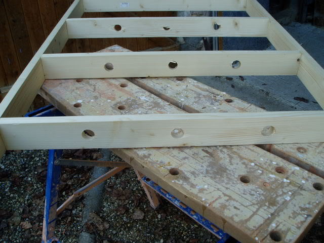
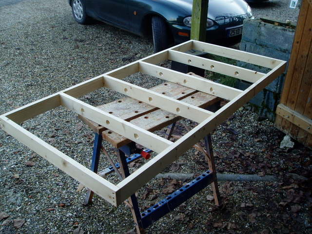
The "basic" framework before adding the risers for the track bed. As you can see, I learn from the forum and there are 3 holes for all the wiring !!
The track bed "datum" is 3.5cm above the framework. As 1 track rises, the other will fall allowing for a track clearance of 7cm in half the normal length.
Hope it works !!
Petermac
'Petermac
Posted
Full Member
Petermac
'Petermac
Posted
Full Member
:oops: :oops: :oops:
Petermac
'Petermac
Posted
Full Member
Phill
Posted
Guest user
Cheers Phill :!:

Posted
Full Member
Phill
1 guest and 0 members have just viewed this.