00 Gauge - Maxmill Junction
Posted

Full Member
Petermac's Railway
Thanks Jeff and Phill - right size now.Petermac
'Petermac

Posted
Guest user
hope it's in the right place :!: :!: :!:

Posted
Full Member
Gwent Rail said
Just to show that I am of some use, I've added your text in the correct place and deleted it from the above post, Petermac.
hope it's in the right place :!: :!: :!:
Thanks Jeff - it looks much "tidier" now. :wink: :wink:
Petermac
'Petermac
Posted
Full Member
Just a sketch but something like the final effort.
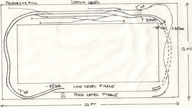
Comments/critical or otherwise would, as always, be gratefully received.
Heaven knows, I need all the help I can get !!!! :wink: :wink: :wink:
Petermac
'Petermac
Posted
Guest user
Bryan
Posted

Full Member
Wayne
Posted
Guest user
looks like you have a reverse loop,top right corner,or am i
mistaken?
:? :?
8)
Posted
Full Member
Bryan said
Reference your posting on the Padstow girder bring thread where would you propose placing the girder bridge on your layout plan?
Bryan
Bryan - the left hand side of the layout is where I propose to put me "bridge" section. The baseboard may be dropped below the normal "datum minus 35mm" here to accomodate either a viaduct or bridge like Padstow. It will be a scenic/river crossing area.
Petermac
'Petermac
Posted
Full Member
owen69 said
nice size layout,plenty of scope to add extras as and when,
looks like you have a reverse loop,top right corner,or am i
mistaken?
:? :?
Owen - I THINK you're right !! :? :? Not too sure. The track from the bay platform (the branchline) climbs a 1 in 45 gradient whilst the doubled mainline falls at the same rate enabling me to cross over somewhere near the tunnel entrance - if my maths are correct !!!
The link from these double mainlines to the branch will, I'm sure, create a reverse loop. I'll have to swat up on the electrics :roll: :roll:
Petermac
'Petermac
Posted
Full Member
Some of it is second hand and has been painted before.
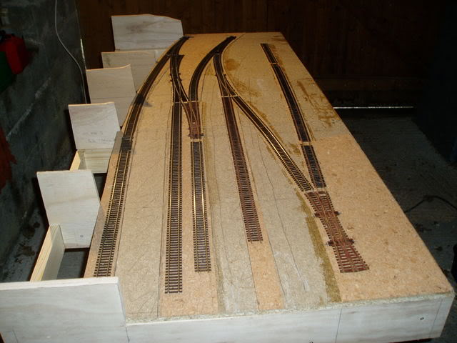
As you view the "down the line" shot, the left hand track terminates in the bay platform and the double slip is in the middle of the goods yard with the track off to the right leading to the proposed cattle dock - well away from the platforms !! I'm not too bothered about the missing sleepers etc. in the goods yard as most of this area will be either paved or tarmac for vehicular access so you'll only see the rail tops.
Beyond, on the next board, we start the gradients taking the branch line over the mainlines.
The foreground is where the 2nd station board and remaining goods yard will be. The formers to the left will carry by a high retaining wall with a road and, hopefully, some low relief building along the backscene.
Petermac
'Petermac
Posted
Full Member
Wayne Williams said
I like the look of all the curved track. Then I noticed the dimensions, wow, very large layout area. You have to duck under somewhere to get inside?
Wayne
I propose to have a lifting/removable/hinged section somewhere on the left hand scenic area Wayne although the boards will be fairly high. It's only for me and I do like to view things from near track level.
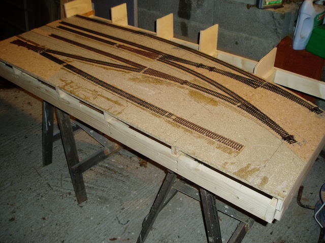
Regarding dimensions, it is a project designed to see me out !!! and we have a huge unused loft area here with loads of headroom. We're currently waiting to have half the roof renewed (beetles do eat wood here in France and over the last couple of hundred years or so, they've had their feast on our roof timbers !!!), because of this, I still don't have a permanent home for it so I'm building it on a modular basis board by board - just hope it all fits together :roll: :roll: :roll: Hence the shots taken on tressles in the garage - doors closed because it is a filthy wet day. Sorry for the lighting and rather grubby surroundings - hardly professional !!
Petermac
'Petermac
Posted
Full Member
At long last you are revealing all :shock: After months of anticipation we see not only a track plan but the start of a layout. Fantastic another layout begins to take shape on the forum. I like the look of the sweeping nature of your design and, unless I am mistaken, you seem to be using large radius points. Thanks for showing us your efforts, and given the size of this project there's much more to come.
Great stuff :) :)
Bob(K)
Posted
Full Member
Phill
Posted
Full Member
It's just fantastic to have made a start and, once I've got another board done (the framework is ready for "topping out") I may just be able to run a loco back and forth - yes guys, "testing" is on the way for Petermac
I've tried to use large radius points Novice - I love them and that's one of the reasons I've had to do so much re-planning. I've got the space so why not ? Some will, inevitably, be medium radius but, for the main lines, I hope I can manage everything in large radius. Once I have a proper "home" for it all, I can really get going - with the "Boss's" permission naturally !! Already, she's complaining that I spend all my time in "chat rooms" or playing in the garage but then, we all have our cross to bear and anyway, she's off to Australia to see her son in 10 days time (we're both 2nd time around :wink: :wink: ) so get ready for more postings !!!!
Petermac
'Petermac
Posted
Guest user
Good luck :!: :!:
Posted
Full Member
(I wonder if i could do that?)
Are you intending to layout all your track on each section beforehand? :shock: :shock: :shock:
Wayne
Posted

Full Member
All my baseboards were built in my garage and just plug together using locating dowels and clips. I can therefore take one (or more) baseboards anywhere in the house that I fancy working on them (in theory, at least). It is adviseable to have adjacent baseboard connected when laying track across the joins because it makes alignment a great deal easier. Lay the track straight across the join, fix it in place, then cut it at the baseboard join.
It also means that I can still turn a board upside down to make fitting point motors and wiring, etc, a whole lot easier.
Perry
Due to cutbacks, the light at the end of the tunnel has been switched off.
Posted
Full Member
I'd have preferred to do it in-situ but, as this isn't now possible (the roof should have been done BEFORE winter but hey guys, this is France !!), I thought about it and remembered seeing Perry's photos of his boards and the dowel connections, I thought "why not"?
Again, exactly as Perry says, I'll build the 2nd board, connect the 2 together, lay short lengths of track across the joint then cut it before separating the boards again. That's why, in my photos, none of the trackwork runs to the end of the board.
The main problems with this system are alignment (I'm nowhere near as accurate as Perry !!) and actually disguising the joint in the scenery. The next "station" board won't be much of a problem because I plan to cover the joint with a "plug-in" over bridge (running from the front of the board to the backscene). The centre line of this bridge will be exactly over the board joint.
Incidentally, I won't move everything into the loft, connect and play when it's all done !! Once all the boards are complete, I'll move everything into the loft, connect it and TEST
Still struggling to name the layout - if anyone has any ideas ?
Petermac
'Petermac
Posted
Guest user
Also like Perry, I've made everything "semi-portable" (well it's moveable if not truly portable :!: )
I've used locating dowels and bolts (like Perry) but have sourced mine from "Red Dog Fasteners", who advertise regularly in Railway Modeller.
These dowels are easier to fit than Perry's, but would not be as accurate as his without the coach bolts.
With both, I've found them 100% reliable.
They come with full instructions, drill sizes needed and clear diagrammes.
As one less than 100% carpenter to another, I would reccomend them to you.
Posted

Full Member

1 guest and 0 members have just viewed this.