00 Gauge - Jeff Lynn / SRman's New Layout
Posted
Inactive Member
Progress (or otherwise) on Jeff's new layout
I must confess to great admiration for those with all these electrical skills, Counting you among them Jeff.That panel looks the business.
regards,
Derek.

Posted
Full Member
My wiring needs a bit of tidying up but I have designed it from the start with some modularity so that it is easily extended or shortened without having to rewire the whole lot.
Jeff Lynn,
Amateur layabout, Professional Lurker, Thread hijacker extraordinaire
Amateur layabout, Professional Lurker, Thread hijacker extraordinaire
Posted
Full Member
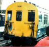
The first two photos show just the 2 BILs, including the third, as yet untouched, NRM version of unit 2090, unit 2147 with full yellow ends, and unit 2134 with small yellow panels. The third photo shows the 6BIL formation with the 'Tin" HAL added. this will receive unit number 2694.


Once Hornby produce their 2 HAL units from the 2014 announcements, the possible formations will be even more interesting.
 Last edit: by SRman
Jeff Lynn,
Amateur layabout, Professional Lurker, Thread hijacker extraordinaire
Amateur layabout, Professional Lurker, Thread hijacker extraordinaire
Posted
Full Member
With all that going on, I decided to have a Network SouthEast (NSE) running session.
In the two photos below, the trains at Newton Broadway are, from left to right, the Hornby class 92, 92 022, on a Speedlink freight (the rear of the train), the Bratchell class 455/8, 455 835, the Bratchell class 319/1, 319 174, and a Bachmann class 416/2, 6225.


From the other end of the station, looking under the rail overbridge, from left to right are 319 174, 455 835, and 92 022.

Last edit: by SRman
Jeff Lynn,
Amateur layabout, Professional Lurker, Thread hijacker extraordinaire
Amateur layabout, Professional Lurker, Thread hijacker extraordinaire
Posted
Full Member
However, while doing this I noticed there was some distortion at two of the section joints, one at each end of the platform. This seems to be a result of the plasticard base expanding in the heat (we are now on our fourth day of 40+ degree Celsius heat, with evening and night temperatures in the high 20s and low 30s). I am hoping I won't have to cut and trim anything after it all cools off again over the weekend (cooler change on the way).


Jeff Lynn,
Amateur layabout, Professional Lurker, Thread hijacker extraordinaire
Amateur layabout, Professional Lurker, Thread hijacker extraordinaire
Posted
Full Member
It should probably really have the Westinghouse electro-pneumatic style of miniature levers but after much thought, I realised that no one would be able to see such a system inside the box anyway, so opted to use the old style levers. With this in mind, I ordered the Smiths/W & T etched brass levers. These were duly assembled over a couple of evenings, with many pauses to cool off again from the heat. I can't say I did a brilliant job with these, but once they are painted they will look OK. The frame was stuck to a small rectangle of 40 thou plasticard acting as a sort of plinth. This was trimmed down a bit once I had the final size of the frame.
I cut a false floor out of 40 thou plasticard, designed to fit the shaped end of the signal box and overlap the recess in the floor/roof at the other end. Onto that I stuck a floor cut to exact shape from Wills' wooden planking.
The wooden floor was stuck to the false floor with solvent, while the lever frame/plinth was then glued towards the front windows of the box, roughly centrally along the floor planking. A small rectangle of black plastic was glued to the shaped end of the box to allow the floor to rest against it and prevent me from pushing it too far upwards.
I will draw up and print a track diagram to mount on the back wall of the box, and add some more furniture for the signalmen to use (desks, chairs, etc.).
Anyway, here are some photos to show what I am talking about.


Jeff Lynn,
Amateur layabout, Professional Lurker, Thread hijacker extraordinaire
Amateur layabout, Professional Lurker, Thread hijacker extraordinaire
Posted
Full Member
I created the diagram in Microsoft Word, using the line and shape tools. I then took a screen snapshot using the snipping tool built into Windows and loaded the resulting image into Paint Shop Pro (Photoshop would be just as good!) for a little 'fettling' and adding the green background.
I then loaded the image back into word and resized it to suit the 40 mm width available on the back wall of the signal box, printed it on the colour laser printer, then cut it out. I cut a 40 thou plasticard panel, slightly over-depth, and glued the printed panel onto the plasticard, then glue the whole panel into the signal box. The result is rather pleasing, I think

Jeff Lynn,
Amateur layabout, Professional Lurker, Thread hijacker extraordinaire
Amateur layabout, Professional Lurker, Thread hijacker extraordinaire
Posted
Full Member

​

Last edit: by SRman
Jeff Lynn,
Amateur layabout, Professional Lurker, Thread hijacker extraordinaire
Amateur layabout, Professional Lurker, Thread hijacker extraordinaire
Posted
Full Member


Jeff Lynn,
Amateur layabout, Professional Lurker, Thread hijacker extraordinaire
Amateur layabout, Professional Lurker, Thread hijacker extraordinaire
Posted

Banned
Cheers, Gary.
Posted
Full Member
A while ago I bought some LED lighting strips from a dealer on eBay (also available from the likes of Jaycar). I bought 5 metre reels of warm white strip and cool white strip for around $AUS15 each. The strips come with resistors already built in and work off 12V DC, and are marked with cutting points and solder pads every three LEDs. I had carriage lighting in mind (Hornby 2 BILs in particular) but they are also ideal for lighting buildings.

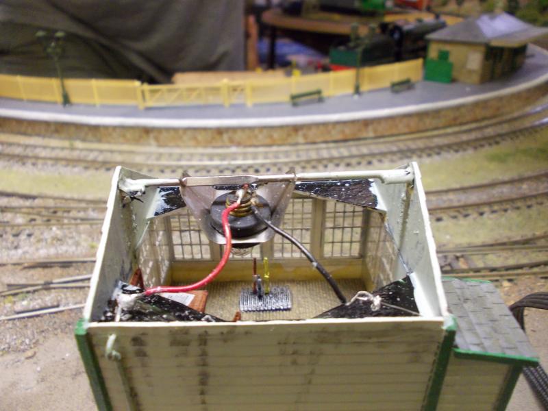
I cut one strip of three Surface Mount LEDs and soldered some wires to it, then mounted it in the ceiling of the signal box - the strips are self-adhesive but they don't stick well to the matte paint I used on the inside of the cabin so I used some black-tack to secure the strip and the wires. I had to file a small semi-circular notch in the floor assembly to let the wires pass through to baseboard level.
I hooked the wires up to my test analogue controller, which has a controlled output but also has 12V DC uncontrolled and 16V AC uncontrolled outputs, noting which was the positive wire as I did so. The result was just a teensy bit bright!!


I could add a higher resistance into the circuit but I thought a diffuser would serve to distribute the light as well as toning it down a bit. Some 10 thou plasticard was cut to fit the ceiling area and Blu-Tacked into place. This was somewhat better.

I still have to add some more fittings and furniture into the box, including something like an armchair, a clock, a couple of phones and possibly a stove. There's also a white metal cat awaiting painting!
You can see the wires running down next to the door. They will be painted to look like pipes.
Last edit: by SRman
Jeff Lynn,
Amateur layabout, Professional Lurker, Thread hijacker extraordinaire
Amateur layabout, Professional Lurker, Thread hijacker extraordinaire
Posted
Banned
Cheers, Gary.
Last edit: by Gary
Posted
Full Member

Last edit: by SRman
Jeff Lynn,
Amateur layabout, Professional Lurker, Thread hijacker extraordinaire
Amateur layabout, Professional Lurker, Thread hijacker extraordinaire
Posted
Banned
Cheers, Gary.
Posted
Full Member
:shock: :shock: :shock:
I did a little wiring this morning, so here it is in situ on the layout.


The lights are still a bit too bright but the overall effect is good.
Jeff Lynn,
Amateur layabout, Professional Lurker, Thread hijacker extraordinaire
Amateur layabout, Professional Lurker, Thread hijacker extraordinaire
Posted
Full Member
I found some spare 6 way 2 pole rotary switches left over from the cab control of my old layout's Middlehurst branch, which would allow me to switch three (or more) controls to the programming track with some 'off' positions to isolate it as well.
So, I have wired the LokProgrammer/computer to one position, the original programming output from my NCE Power Pro system to another position, and a Power Cab to a third one - the Power Pro 'talks' properly to the computer allowing full read back and programming from Decoder Pro on the computer, whereas the Power Cab has some limitations on this through its USB interface but, on the other hand, the Power Cab has a little more 'oomph' for programming sound decoders.
I could also add a 12V DC output to one of the spare pairs of terminals on the switch too, which would allow me to use the rolling road and run DC locomotives in before chipping them.
The switch was mounted on a piece of stout plasticard and a label printed up on the computer, with a little trial and error to get things to line up satisfactorily. It's not perfect but it works well and doesn't look too bad.
I must label that Power Cab Panel to ensure that no one tries to use it to drive the layout - it is programming track only


Jeff Lynn,
Amateur layabout, Professional Lurker, Thread hijacker extraordinaire
Amateur layabout, Professional Lurker, Thread hijacker extraordinaire
Posted
Inactive Member
Its amazing how many gadgets have got into model railway builds with the event of the two wire system.
I have yet to try fitting a decoder, I just look at my DCC control packages challanging me to open them.
Those wires look very tempting as playthings for Toby!
Keep up the good work,
Derek.
Posted
Full Member


The main (large) side grilles on the new version are a little too prominent but overall it does look better than the original. I particularly like the new bogie side frames, although the brake blocks are still not in line with the wheel treads. It is nice to have the original roof layout modelled properly too.
I did a little extra wiring to the programming/test track to include a controlled 12V DC supply, using one of the erstwhile neutral positions on the switch I showed in my post of Monday 27th January (post #316 http://yourmodelrailway.net/view_topic.php?id=7883&forum_id=21&page=16#p212486). This allowed me to set up the rolling road and run the locomotive in a bit on DC before fitting a decoder.
D6570 is currently fitted with a TCS M1P decoder, after burning out a cheap Hattons one! I will try to get something a little beefier to replace the TCS one but I have run out of good quality 8-pin decoders (I usually like ESU ones for Heljan locos but Lenz are also ideally suited). I do have plenty of good quality 21-pin decoders in stock but they are of no use here!!
Last edit: by SRman
Jeff Lynn,
Amateur layabout, Professional Lurker, Thread hijacker extraordinaire
Amateur layabout, Professional Lurker, Thread hijacker extraordinaire
Posted
Full Member
It is seen here on 'menial' engineers' duties!

Jeff Lynn,
Amateur layabout, Professional Lurker, Thread hijacker extraordinaire
Amateur layabout, Professional Lurker, Thread hijacker extraordinaire
Posted
Full Member
There is still much to be done but each time I do these little tweaks and adjustments and rearrangements, it gets a little better and just a little closer to being finished. Ignore the glue bottle - it is fulfilling a useful function there by holding a section of roadway down while the glue sets!


Last edit: by SRman
Jeff Lynn,
Amateur layabout, Professional Lurker, Thread hijacker extraordinaire
Amateur layabout, Professional Lurker, Thread hijacker extraordinaire
1 guest and 0 members have just viewed this.