Monthly Project - December - 2011
Posted
#131708
(In Topic #6979)

Legacy Member
Stu's Tumbledown Shed.
OK folks, anyone up for the December project, last one of the year. This is open to all members of course, new or old.
Posted

Full Member
The tumbledown shed !
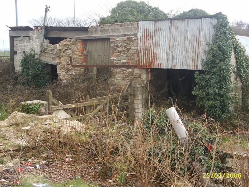
As you can see from the date, this has been a long time project of mine, I've just never gotten around to it. For those of you in Cornwall, it can be found immediately to the west of the Pizza Hut restuarant, Maiden Green, Truro.
Construction will begin shorty, using printed paper, card, plasticard and anything esle I need to represent the myriad of textures and construction materials used to create this (to my eyes) delightful building.
Stubby47's Bespoke Model Buildings
All photos I post are ©Stu Hilton, but are free for use by anyone.
Posted

Full Member
Looks like you left the gate open after you took the photos………………
'Petermac
Posted
Legacy Member
Posted
Full Member
(Apologies if any of the following seems to be a bit basic or obvious - but this how I do things and I'll try to explain the what, the why and the how for each section.)
What I tend to do first is examine the prototype and try to identify all the possible different elements that make up the whole.
As we can see, there are (at least) 20 constituent parts or materials which will need to be replicated, using whatever seems to be the most appropriate medium.
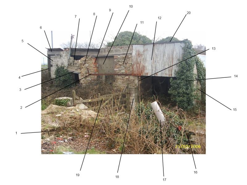
From the left working clockwise :
1: Dry stone wall / cornish hedge - large flatish stones with earth filler
2: Rusty iron bar - used for supporting the wriggly tin, itself supported by a wooden beam
3: Wooden beam as doorway lintel
4: Wriggly tin cladding
5: Breeze block wall
6: Heftly wooden beam
7: Breeze blocks - these are very eroded, leaving concave faces and the mortar exposed
8: Rough stone walling
9: Red brick in-fill on the window surround
10: Painted wriggly tin blocking the window
11: Stone walling - not as rough as the other part, reasonable mortar
12: Rusty wriggly tin as cladding
13: Large stone quoins
14: Ivy
15: Regular blockwork as the side wall
16: An old wooden 5-bar gate
17: A new-ish plastic pipe
18: Modern bricks used to make gate post pillar
19: 5-bar gates, with extended inner vertical bar and secondary diagonal strut
20: Wriggly tin used as roof
In addition there are lots of brambles and other brown undergrowth (the photo was taken in February). Although there is no one main feature to the building, there are lots of elemnts which will help to create the overall effect. For example, there are three sorts of blockwork (#5, #7 and the larger blocks over the window) - these will need to be created using different techniques.
I'll make the building with a decent depth, to alow me to add the inner wall and create a dark interior. The front 'wall' will also need to be of sufficient thickness to show the exposed brickwork and the relief for the window. As such I might make the model wall out of two layers of mount card with a spacer layer.
To make all the various textures I'm going to need lots of varieties of printed brick / tin, plus wood coffee stirrers, plasticard and small stones.
The next stage, therefore is to try to source these things.
Stubby47's Bespoke Model Buildings
All photos I post are ©Stu Hilton, but are free for use by anyone.
Posted

Inactive Member
It's a serious request. I've never been able to figure it out. :oops:
Max
Port Elderley
Port Elderley
Posted
Full Member
Stu, after this can you do a tute on how to put the lines/numbers/comments on to a photograph, please?
It's a serious request. I've never been able to figure it out. :oops:
Hi Max,
I use a free program called 'Paint.Net'. http://www.getpaint.net/
I took the original photo and then increased the canvas size (not the Image size) all around to give me some white space. Using the simple Line Tool, I drew lines from the point on the photo to the white area, then used the Text tool to add individual numbers at the end of each line.
I can create a full step by step guide if you need one, but have a go first - it really is that simple.
Stu
Stubby47's Bespoke Model Buildings
All photos I post are ©Stu Hilton, but are free for use by anyone.
Posted
Full Member
'Petermac
Posted
Inactive Member
Max
Port Elderley
Port Elderley
Posted
Inactive Member
Max
Port Elderley
Port Elderley
Posted
Full Member
As the actual site is private and also marked as dangerous (due no doubt to the state of the shed !), I've not got any physical sizes. However, it is relatively simple to guestimate some basic dimensions, bearing in mind this model will not be a 100% accurate one, just a reasonable representation.
There are two entrances to the shed, one via the very lopsided door way and the other under what remains of the tin cladding; door ways are usually big enough to walk through, so at least 6ft high. Generally, a 5 bar gate will be at least 4'6" high (think about where it would come up to if you stood next to one), so from that we can guess that the bottom edge of the cladding would be at least 6ft, probably 7ft, from the ground (which we can't actually see…). That would make the cladding itself (from a quick measurement on another, square-on, photo) about 5'5".
(Ground to cladding measures 85mm, which equates to 7ft, so 1ft equates to 85/7 approx = 12mm. The cladding measurement is 65mm, which is 5.4 ft, which is about 5'5").
Overall, the building 'measures' about 29ft wide by 12'5" high - in 4mm scale this is (rounded up) 120mm x 50mm.
So, after a bit of sketching, we get this :
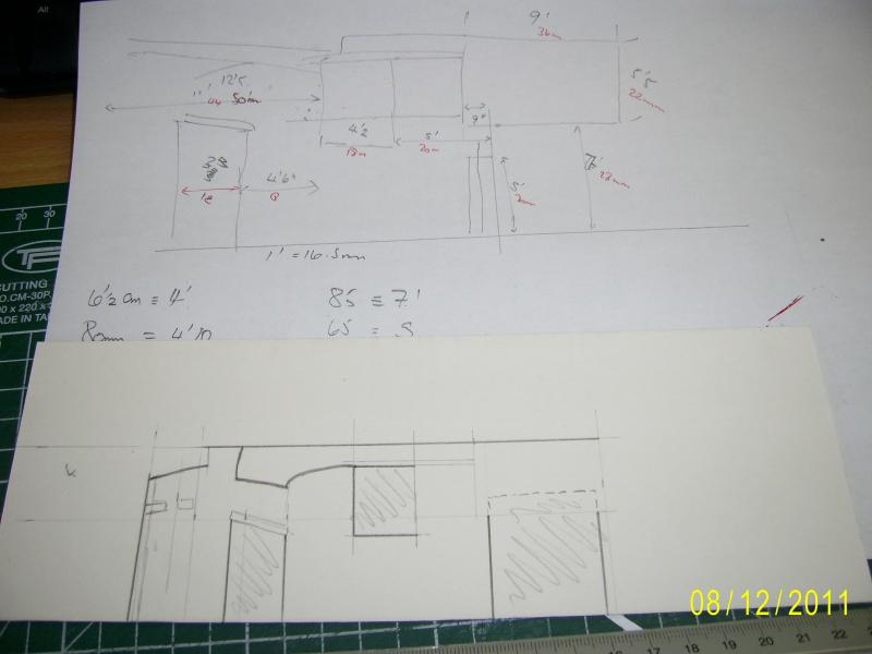
On a rough sketch of the building I've added the real measuments (in feet) and the model measurements (in mm and in red ink), then transferred these to a more accurately sized drawing on a piece of card. This will form the main part of the front wall.
 Last edit: by Stubby47
Stubby47's Bespoke Model Buildings
All photos I post are ©Stu Hilton, but are free for use by anyone.
Posted
Full Member
 :thumbs
'Petermac
Posted
Full Member
Elementary, my dear Watson…I'm following this with great interest Sherlock …………..
I've been thinking about where on a layout I might site this model. Using the 3ft rule, if I place the shed at the back of the baseboard, the use of paper to represent the wriggly tin would probably be ok. However, as I'll probably be siting this near the front, and there is a quite obvious end-on view of the roof, I'm tempted to use the Slater's plasticard version instead of the Scalescenes paper one.
Another area I've been musing about is the small section of eroded brickwork, over the small door, where the mortar is exposed. Without actually trying it yet, I'm considering using some South East Finecast walls, but in reverse, so the mortar stand outs.
I find that this sort of pondering lets me resolve problems away from the workbench, so the finite time I have to actually model is more productive.
Stubby47's Bespoke Model Buildings
All photos I post are ©Stu Hilton, but are free for use by anyone.
Posted
Full Member
Now that sounds interesting. Are the reverse details good enough ? My experience with Slaters stone sheets is that there's almost no detail on the reverse at all - just a "wobbly" piece of plasticard ……………. Maybe SEFC is higher quality :roll:……………………………………………………….
Another area I've been musing about is the small section of eroded brickwork, over the small door, where the mortar is exposed. Without actually trying it yet, I'm considering using some South East Finecast walls, but in reverse, so the mortar stand outs.
……………………………………………………….
An advantage of using card for the wriggly tim would be that you could bend it across the corrugations … You often see old sheets buckled "the wrong way" and I doubt you could do this with plasticard. Without going back to your photos (I'm on "edit" mode), maybe there aren't any sheets like that on the prototype.
'Petermac
Posted

Legacy Member

Bozzy(never known to pass a pub)
Posted
Full Member
Stubby47's Bespoke Model Buildings
All photos I post are ©Stu Hilton, but are free for use by anyone.
Posted
Inactive Member
I could post you over some if you can't get it there.
Max
Port Elderley
Port Elderley
Posted
Full Member
Stu, regarding your "wriggly tin" (in Oz it's called corrugated iron) - we have a manufacturer here called a.m.r.i. who make styrene sheets of it in various scales.
I could post you over some if you can't get it there.
Thanks Max, I was unsure of the spelling of 'corrugated' (but now I know:thumbs), so used the term wriggly tin instead.
As for supply, Slaters make a decent enough version, which I obtain from Kernow Model Rail Centre, but many thanks for the offer.
So, onwards with the build.
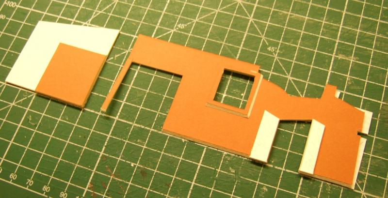
Following the marking out, the next stage is to cut the front wall.
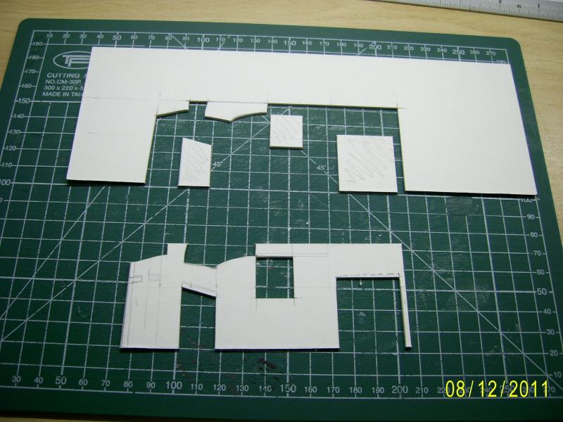
The pieces I cut out are used again to double the thickness of the card around the door frame, another piece is used for the window frame.
I've also cut the right hand end wall and added an internal piece to double the thickness.
Stubby47's Bespoke Model Buildings
All photos I post are ©Stu Hilton, but are free for use by anyone.
Posted
Full Member
[user=465]Stubby47[/user] wrote:Now that sounds interesting. Are the reverse details good enough ? My experience with Slaters stone sheets is that there's almost no detail on the reverse at all - just a "wobbly" piece of plasticard ……………. Maybe SEFC is higher quality :roll:……………………………………………………….
Another area I've been musing about is the small section of eroded brickwork, over the small door, where the mortar is exposed. Without actually trying it yet, I'm considering using some South East Finecast walls, but in reverse, so the mortar stand outs.
……………………………………………………….
An advantage of using card for the wriggly tim would be that you could bend it across the corrugations … You often see old sheets buckled "the wrong way" and I doubt you could do this with plasticard. Without going back to your photos (I'm on "edit" mode), maybe there aren't any sheets like that on the prototype.
Here is a photo of the SEF brickwork, showing the reverse side. I've tried to add a bit of colour to highlight the shape.
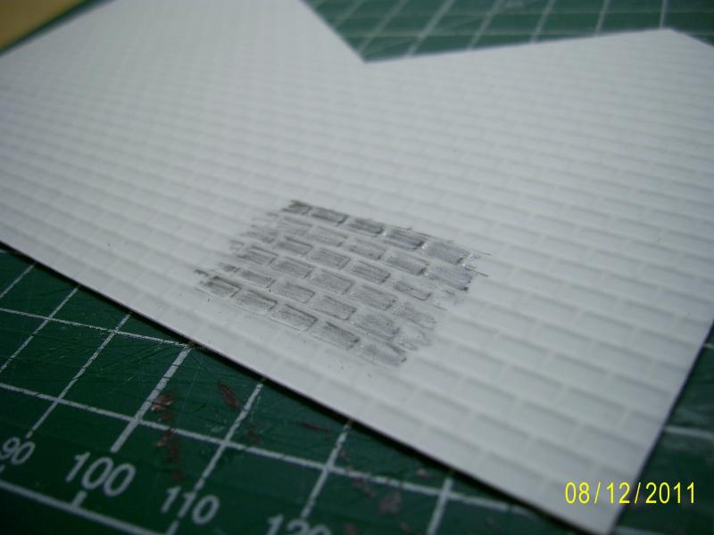
As far as I know there are no curved sections of corrugated iron sheeting on the prototype, but the Slater's sheet is fairly thin and could be bent, provided the curve is not too sharp.
Last edit: by Stubby47
Stubby47's Bespoke Model Buildings
All photos I post are ©Stu Hilton, but are free for use by anyone.
Posted
Full Member

What I should have done at this point was to complete the rest of the stone cladding on the wall but, being impatient, I cut a back wall and second side wall, and stuck them together…

The next stage then was to add the main stone cladding. I considered adding individual slivers of plasticard to represent the prototype, but settled instead for a small stoned plasticard sheet. Painting later will help to disguise this and make it look more like the real thing.
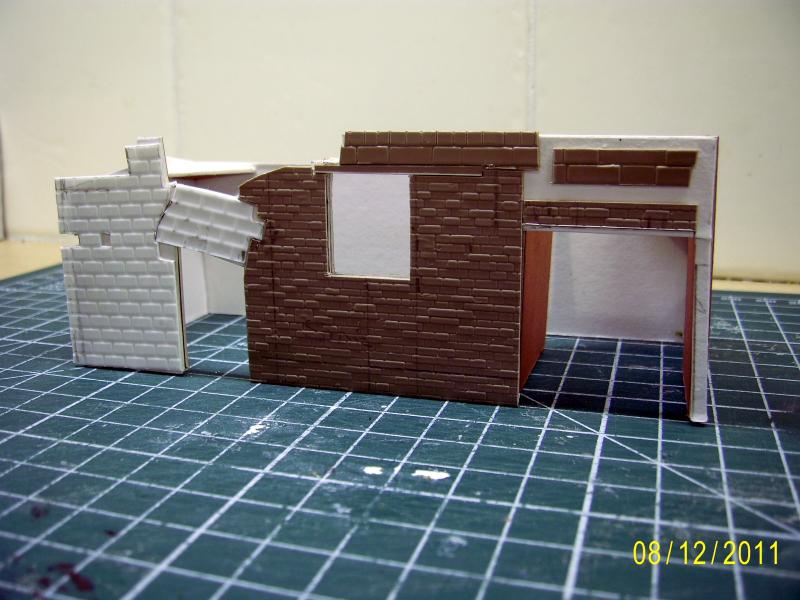
You will notice the left hand block work is slightly at an angle, as on the prototype, there is a cut out below the reverse blocks to allow a lintel to be added after painting, and a liontel and upper breeze block wall has been added ovr the window.
The two odd pieces of cladding over the larger door way are to provide a level surface onto which to stick the corrugated iron cladding.
The next stage is to paint the walls, then I can add the various detailing bits.
(Hope some of this is making sense to someone.)
Last edit: by Stubby47
Stubby47's Bespoke Model Buildings
All photos I post are ©Stu Hilton, but are free for use by anyone.
1 guest and 0 members have just viewed this.