Going large - building large layouts
Posted

Full Member
"2 wires to the track"
This photo showed up the uneven sidings - I had not pinned them down!! The usefulness of taking pictures - they show up your shortcomings and omissions!!
Bashing on…….
Shed dweller, Softie Southerner and Meglomaniac

Posted

Full Member
'Petermac
Posted

Full Member
Might make trouble shooting the wiring a bit tricky though!
:lol:
Posted
Full Member
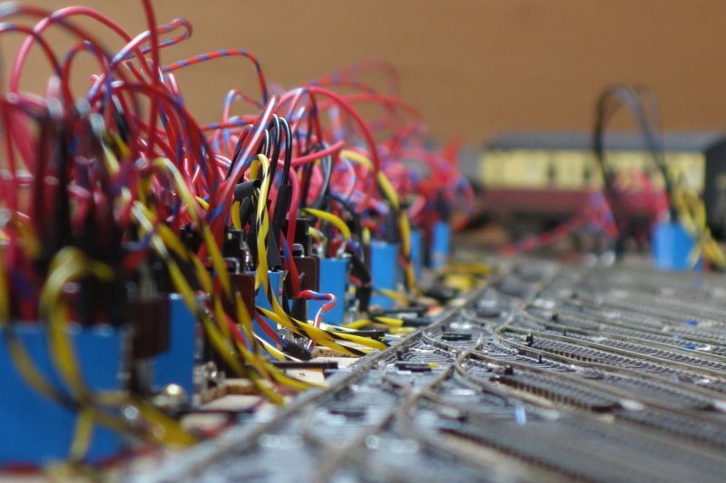
I'm up to about 1600 metres of wire :shock: :shock:
There are, as I have said, 5 wiring circuits to instal and, so far, the frog polarities are done, the relay power and cascades are done and tested, the LED cascade was finished last night and tested (only 1 pair of wires reversed out of 32 pairs), the point motor wiring is over half done and the "links" circuit for the slow-down and isolator sections is nearly there (more wire needed). I estimate that, by this time next week, all of these circuits will be done and then I get 4 days of "shed time" as Mrs M heads South for a catch-up with old work colleagues.
I am hoping that 4 days will allow me to paint the inside of the shed, set out and lay Middle Junction and make a start on the central peninsular baseboard that will carry Trinity Square and the branch. I don't need to lay those lines just yet but the alignment of the main line for Yarslow can be determined by Middle Junction. Also, the peninsular boards will have storage space underneath that clears a lot of stuff out from under my feet. That includes the heavy, immovable pile of boxes containing my magazines - getting them out onto shelves will be an hour well spent to re-gain my "resource library".
I am not setting myself targets and goals but I am anticipating quicker progress around the main circuit and so the plan of getting something running on the main line by the end of the year is looking easily within reach. In fact, by then, I anticipate having all of the Yarslow track laid and wired.
Bashing on……..
Shed dweller, Softie Southerner and Meglomaniac
Posted
Full Member
Regarding your magazine "resources", have you indexed them ? When we moved to France, I brought half a lorry load of similar "resources".
When we moved from that house to what had been our letting house, most of the unopened boxes of "resources" went in the skip. They'd been "in store" for 17 years !
'Petermac
Posted
Full Member
My magazines are fully indexed - they start from Janaury 1972 when, as a young lad, I bought my first edition after having been "good" at the dentists!!! God Bless my Mum - I wonder if she realised what she had started………
Barry
Shed dweller, Softie Southerner and Meglomaniac
Posted
Full Member
Worst mistake I ever made, butchering all those magazines - I filed the "interesting" articles in ring binders in clear plastic wallets and never looked at them again. Too difficult, but looking through a bound magazine is much easier and interesting - and you never know what articles are going to become interesting to you.
Alan
Posted
Full Member
I share your pain!
I did have quite a collection of MRJ's, Model Railway Constructor, British Model Railways and a whole load of other odds and ends bought for car/plane/train journeys. I cut those up into bits for a scrap book and discarded everything I didn't want. Somehow, I couldn't bring myself to do the same with the RM's.
I don't hoard anything and, in fact, keep very lightweight "bits" boxes of railway stuff. Quite where my attachment to the RM comes from, I don't know.
Barry
Shed dweller, Softie Southerner and Meglomaniac
Posted
Full Member

Its the Bachmann Scenecraft NER loco shed which I wanted for Trinity Square. I know that I could have had a go at building one and that this costs the same as a decent unchipped loco but it's perfect for what I want and I am keen to fight the battles I know I can win. Scratchbuilding something on this scale to get this outcome is not a fight I back myself to win.
[slopes off in shame…….. :oops:]
Sloping off…………..
Shed dweller, Softie Southerner and Meglomaniac
Posted
Full Member
Posted

Full Member
In researching my new project, the resources I've had access to just a mouse click way are so diverse and many I can't imagine how I'd have managed as a very late newcomer to the hobby. To cite a few examples that I've already referenced over on my topic.
I was looking for inspiration and the thinking behind the design of various well known layouts. First a much loved former YMRC member had posted his own "how to" website. When that proved a bit thin on the details about Ops I went further, finding (on line) a reference to an article in RM and amazingly one for sale. Before committing, I searched further and to my delight found that some relevant bits and much more had been carefully stored away in the Gallery on here, just waiting for me!
John Ahern's classic layout is well documented by some online reprints of very old Railway mags, Then videos of a more modern BTW setting operating in a Show and on a visit to Pendon, both great help.
Imagine being able to find even a fraction of such treasure buried away in dusty old boxes of mags. Besides, if they were here it'd be my luck for termites to have digested them first.
 Last edit: by Colin W
Posted
Full Member
Apologies, OT :off topic but we need a bit of levity in these times.
"2 wires to the track"
This photo showed up the uneven sidings - I had not pinned them down!! The usefulness of taking pictures - they show up your shortcomings and omissions!!
Bashing on…….
[yt]iXaw70X7wb4[/yt]
When Barry turns on the power, this comes to mind.
My kids favorite, watched every Christmas.
Last edit: by Colin W
Posted
Full Member

In fact, because of the cascading principle, only 4 relays and 4 LEDs maximum will be active at any one time so the current draw will not dim the lights all over Merseyside!!
Shed dweller, Softie Southerner and Meglomaniac
Posted
Full Member

Having made a rick of the old control panel by putting the triple isolator sections on the wrong track (schoolboy error), I have now re-made the main line loops storage panel and this is the mock-up. The switches, LEDs and push buttons are in and the wooden numerals glued down but not the letters. I am not keen on the flamingo pink put this is only colour I have. Some of the push-buttons need a tweak to get them to line up better.
The letters here are plastic and denote "Main Line" in red/pink for the up line and blue for the down as per the wiring convention. The UP and DOWN letters are a pathetic shade of pink but they will do. I bought these letters ages ago from a craft shop. The red numerals came from The Works - a remainder bookshop outlet we have in the UK and always a good source of cheap crafty stuff like letters, numbers and similar stuff. Its always worth a look in if you are passing. The wooden numerals are 1mm thick and probably laser cut. The bag contains about 100 numbers and they cost £2. Bargain!!
The blobs are actually 5mm 12v green LEDs which I am running from a 6v supply. The "X" relates to the crossover giving access from the TSQ approach line to the down main. The crossover is controlled by the second storage panel (see below) but a warning that this crossover is set to "reverse" appears on this loops panel - a red LED as an extra warning.
The storage sidings will have a second panel for the loco storage and Trinity Square sidings with a separate panel-mounted twin Gaugemaster controller. I will tackle this when the loco/TSQ sidings are laid but this is likely to be after I get the main line done.
I am now facing my first mental challenge thrown up by the size/complexity of this layout. The storage sidings main line loops panel pictured above will be connected to the wiring from the storage area - 176 wires in all to power points, LEDs and isolator sections. If I am to have a mimic panel at my work bench (one of the things on my "want" list for the layout), then I need to replicate this panel. The physical panel is easy enough but 176 wires running about 5 metres around the shed equals another 880 metres of wire. I have managed to find 1000 metres in two reels of weird colours on eBay for £90 - surplus from some other mega project. Leaving the wiring convention aside, this is a weeks work but I am wondering if it's worth it. Without this panel, I just have to walk around the peninsular and press a few buttons to change trains. On the other hand, sitting at the bench working and having trains "on tap" so to speak is a big attraction! I am going to stew on for a couple of days.
Last night I laid the exit tracks at both ends of the storage sidings - those at the Up end connect to Middle Junction which is my next project. Wiring up 4 sets of points, 2 crossings and 3 single slips - all with live frogs and potentially connected to 3 different controllers. What could possibly go wrong?
Bashing on……….
Shed dweller, Softie Southerner and Meglomaniac
Posted
Full Member
I guess the small section of wire would be sufficient for voltage, currents and distance involved for the panel indicator LED’s but not points and isolation sections unless relays used.
Barry T
Last edit: by Barry Taylor
Posted
Full Member
In the meantime………
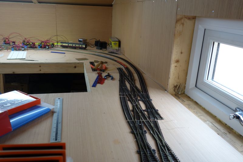
…Middle Junction has been laid, wired, tested and connected to the storage area. Trains can now run down one side and almost across one end of the shed. The live-frog crossing in the foreground provoked much thought. I was minded to drive the changes in polarity by relays switched by the point motors on either side but it is possible, with the point motor pairings I have, to set up a conflicting move across the Down line and thus I would have had to create an interlocking design to avoid this. In the end, I simply isolated it from all the trackwork around it and will use a 4-pole switch to set the polarity of the stock rails and crossing rails. The two options are (a) Main Down line or (b) cross to Trinity Square. The switch works just fine!!
I laid the track and installed the Seep point motors before I screwed the baseboard down. That made it much easier to work on. Although other baseboard pieces are bigger than this one, I might carry on the track laying for Yarslow in the same way.
The next job is to plan, lay out and draw the tracks on the Yarslow boards, planning the approach curves at the branch end and concentrating on getting the 3-degree angle of slant right. That slant allows the platforms to sit at the back of the baseboard nearest the door but brings the tracks forward to make room for the branch as Middle Junction is approached. I reckon getting Yarslow right is going to take a "fair few coats of looking at" :lol: :lol:.
If I get bored, the new control panel is ready for installation so I can start to connect the 176 wires to it…

Bashing on…….
Last edit: by Barry Miltenburg
Shed dweller, Softie Southerner and Meglomaniac
Posted
Full Member
Here is the SEEP point motor wiring underneath Middle Junction.
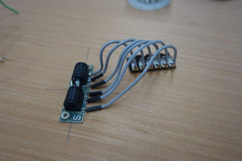
The tag strip is hot-glued down. Note the cross-hairs drawn around the 7mm baseboard hole through which the operating rod passes. The cross-hairs make fixing the motor unit a piece of cake - especially when you can turn the baseboard over like this!!
Barry
Shed dweller, Softie Southerner and Meglomaniac
Posted
Full Member
A couple of questions/comments if I may - those cross-hairs are certainly an excellent aid in lining SEEPs up - they can often be tricky and there's not much room for error if they're to work well. My question is, how do you draw them accurately on one side of the boards when the track is out of sight on the other side …………….. ? The operating rod has to be dead centre and the motor mounted at right angles to the track. I found doing that extremely difficult when I couldn't see the track. I ended up drilling small holes through the baseboard to mark the exact longitudinal position of the point. I have a metal jig to mark the exact position of the motor once I have that first longitudinal line drawn It was getting that first line spot on that caused problems ……………….. :hmm
Second comment - initially, I too used tag strip but quickly discovered that, if I needed to switch the frog polarity when wiring it all up, it was far easier to use choc blocks as the terminal - all one had to do to change polarity was swap 2 wires over. Soldered joints don't easily permit that ……………….. Just a thought before you solder hundreds of them ……….. :cool wink
'Petermac
Posted

Site staff
Ron
NCE DCC ; 00 scale UK outline.
NCE DCC ; 00 scale UK outline.
Posted
Full Member
I, like you, drill 2 small holes to mark the ends of the tie bar and join the dots to give the alignment. The hole for the operating rod is a little trickier and best done first;
- get the point in the right position - use a single pin if neccesary to hold it still
- centre the blades
- using a small drill, drill through the hole in the centre of the tie bar to give the centre of the operating rod hole
- drill a 7mm hole for the operating rod.
I have used choc blocks in the past but suffered failures either when using (soft) copper wire or when tightening down the screw too enthusiastically. I decided to go tag-strip this time after experimenting on a small layout and finding a better success rate. I also find it easier to connect multiple wires together using tag-strip or to create a "spur" by cutting the wire and inserting a tag. No right or wrong answer of course.
Sol - I'm too old in the tooth for all such modern ideas!! Give me a pot of Fluxite and several hundred feet of wire and I'm happy :lol: :lol:
Barry
Shed dweller, Softie Southerner and Meglomaniac
1 guest and 0 members have just viewed this.