Going large - building large layouts
Posted

Full Member
Sounds a simple idea - the best ones usually are - that I will explore. Some of my cartridges are 66 inches long so integrity will be a key factor of success. I might have a scout around the DIY sheds and builders merchants for ideas and suitable material.
What did you use to fix the track down? Most of these conduit plastics are quite greasy.
I was going to use wood as the current train list only requires 10 or so cartridges but they do require a bit of construction so ready made troughs have some appeal!
Barry
Shed dweller, Softie Southerner and Meglomaniac

Posted
Full Member
Posted

Full Member
Staying on the thread Kevin.
Posted

Full Member
Try light fine sanding to roughen the surface and remove any production additives then it should glue with standard epoxy. I find Superglue tends to be too brittle for anything subject to a shock or sideways pressure, very good glue though it is.
# an inert cheap filler like calcium carbonate, aids UV resistance as well
If by any chance it's polypropylene or one of the polythene family then there's little hope for successful gluing. These polymers have very poor UV stability and this is why PVC is generally favoured in these outdoor applications.
 Last edit: by Colin W
Posted
Full Member
Pound shop super glue was used to fix the track in position each end of cassette on about three sleepers, so far OK.
This has been a case of putting a concept together as it went along and off the top of my head so no drawings or design just a few basic measurements for train length.
Barry T
Posted
Full Member
Posted
Full Member
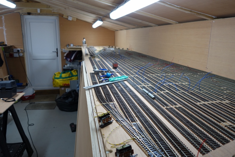
The storage sidings for Trinity Square are now in - 4 in the foreground for the passenger trains, back left (beside the bottle) are two long sidings for parcels and vans trains and back centre, the sidings for the Wythesney trains - a ficticious end-on connection with an ex-L&Y branch. This allows me to run my few ex-LMS engines or treat myself to an open-cab 0-6-0T or LNWR 0-8-0!!
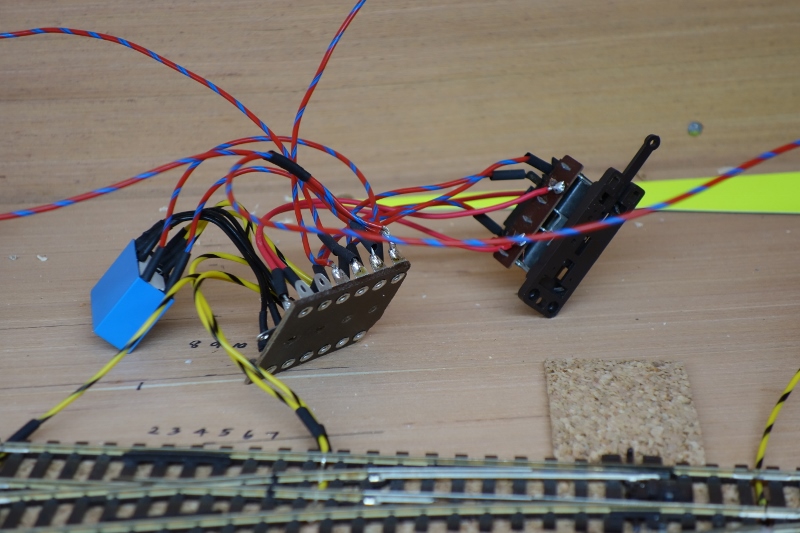
The first 8 point control boards are now fully wired and need fixing down. The point motor will be screwed and the board/relay combination fixed with the hot glue gun. On reflection, whilst I built these on the bench, I will build the next 24 in situ to avoid the birds-nest of wiring! I will complete the heat-shrinking once everything is in and tested,

As she came out of the storage box first, J52 68878 had the honour of being the first engine to run through the pointwork to check frog polarities. Without power to the relays, they are in "passive" mode and with the points in the "normal" position, polarity is correct. I powered the relays (switched on and off via the point motor switches) and proved that the relays are working to change polarity as the point motors change.
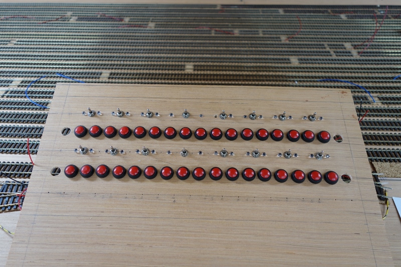
Finally, I have made the control panel for the loops. The upper switches, buttons and LEDs are for the Up line and the lower set for the Down line. The switches operate the points with the LEDs either side confirming that the points have thrown. The four large holes will house LEDs advising when the main continuous run is set. The red push buttons provide power to the isolator sections in each of the storage sidings - 34 in all. Note that track Up4 and Down4 each contain 3 trains - these are the stopping passengers in each direction. I needed to build this to enable the points to be motorised. With 34 isolator switches, 16 sets of points and 36 LEDs, you can imagine the amount of soldering practice I am going to get this week!! I also need to make another 24 point control boards - the first 8 taught me how to make them and I reckon each is about 20 minutes work.
Having built this, I have decided to add another twin track control panel to the storage area leaving the existing panel controller for the Loco storage/Trinity Square sidings area. That way, if I get an operator for this area, he/she can run trains around the main line independent from whatever shunting activity the Yarslow operator is engaged in. It also allows him/her to run 2 trains on the main circuit and still have a controller free to organise the Trinity Square trains and engines. This panel will be duplicated at Yarslow so that I can run the main lines from my work bench.
This coming weekend, Mrs M is off to London for a friends wedding so I will have 3 days camped in the shed. Beer in the fridge, Pizza Hut on speed-dial - what more could I want!!
Bashing on………..
Last edit: by Barry Miltenburg
Shed dweller, Softie Southerner and Meglomaniac
Posted

Full Member
Posted
Full Member
Staying on the thread Kevin.
Posted
Full Member
Posted
Full Member
I cant wait to see it running either :lol: :lol: :lol:
Full on weekend despite it being really hot here. The shed is a few degrees warmer than outside with the cold air fan running and the window/door open. If we get a really hot summer then I must instal the extractor fan that's still sitting in its box.
The wiring in the storage sidings is actually 5 seperate circuits and I have tried to tackle each in turn.
- The frog polarity connections and electrofaffing required for live frog pointwork is all done and sorted. The polarity is actually changed by the relays but in Normal/Passive mode, all pointwork leads to the continuous run so I can run something to test it works (see previous post)
- The power to the relays through the Peco PL-13 switch that's driven by the motor. This power is cascaded so that in Normal/Passive mode, the switch sends the power to the next switch but in Reverse/Active mode, it send it to its own relay.
- The point control wires - these make the points change and will be familiar to anyone who uses powered solenoid point motors. I know that Peco is old-school but they are robust and cheap - a useful combination when you need 40-odd just for the storage sidings!
- The wiring for the LEDs on the control panels. Again, cascaded and driven by the relays so when all the points are in Normal/Passive mode, the LED lights for the continuous run. If any point is Reversed/Active, the power if fed to the LED for that track. One LED per point so 2 per storage track plus the main line - that's 36 wires into the control panel just for lights!
- What I call the "Links" wiring - on each storage track section, a wire from the live rail feeds the 12-inch "slow-down zone" via a 20 Ohm resistor and then the isolator section via a push-button on the control panel. 34 storage sections is another few miles of wire.
A major scare earlier when I wired the first "slow-down" zone only to find it didn't work! I checked my maths (Ohms Law and all that) which suggested I should see a significant speed drop. Turned out one stray strand of the multi-strand wire had bridged the tag strips thus by-passing the resistor. Once sorted, all was well although the older X04 powered Hornby engines were less affected - probably because they pull about 2Amps each and 20 Ohms makes no real difference to them.
I needed something newer to use as a test engine and Hey Ho………..
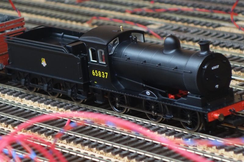
the postman delivered an Oxford Rail J27 - its been on pre-order at Hattons since Xmas 2019!!!!!!!
Haven't had a chance to do a full "review" of it yet but it runs really sweetly and you could see a marked slow down as it ran into the "zone" before hitting the isolator section and stopping. I have another one of these with the late crest and two of the J26 sister engines on pre-order as well - if they are as good as this one, I will be a happy bunny.
Bashing on………..
Shed dweller, Softie Southerner and Meglomaniac
Posted

Full Member
Michael
Posted
Full Member
Its the stuff of dreams! I get by with three tracks per direction! I would have to buy more stock to support the yards above!Goodness gracious me!! What a storage area! And a very fine job of it all too. This is going to be amazing.
Michael
Looking great Barry.
Posted

Full Member
What centre spacing have you allowed between your storage tracks ? Are you able to access a single wagon/carriage on the middle track ? Sure as eggs is eggs, that's where one will decide to jump the rails ……………
Having studied those fabulous sidings, I was slightly taken aback by your test wiring Barry - I had expected "aerospace" type neatness, each carefully labelled with one of those "box" labels of yore ………. :hmm
I note that you too have addressed the "bird's nest" situation and plan to build future ones in situ. Everything else is so neat, the wiring really should follow suit. :thumbs
I've been thinking about one of those Oxford Rail J27's for Maxmill so would be very interested in your review. The current Maxmill demands much smaller locos that the previous version could handle but small transition BR Eastern Region locos seem unpopular with the RTR market. On the same vein, what make is the J52 - she looks nice. :thumbs
'Petermac
Posted
Full Member
Alas, despite my best efforts, the connection of a board containing 13 tag-strips, a relay with 6 pins, a point motor with 3 terminals and a point motor switch with 3 terminals did not connect together with aerospace-standard wiring neatness

The solution would have been to set out the tag strip in the same shape as the various switches and pins or to use much longer wires for each connection. Neither happened, either in the interests of cost or space. Some of the control boards are actually glued to the "backscene" in the absence of real estate beside the point.
The loop tracks are at 1 1/4 inch centres - this is the minimum allowed using code 75 small radius pointwork. Extensive testing with outside cylinder engines prove that its enough. The tracks were laid dead straight and centres checked every couple of feet to avoid issues, including derailments. My track laying is good enough (he says, touching wood, crossing his fingers and hopping on one leg all at the same time) to avoid derailment and the stock is all veteran of the old layout where errant vehicles were sorted or withdrawn from traffic. The last "dodgy" vehicle, the old Triang Weltrol & crane from the Engineers train has just had a new chassis, donated from a more modern version of the same wagon - I married the old repainted crane with the new Hornby version chassis.
The J52 is actually the very old Hornby engine, weathered and detailed with a crew. The body sits about 2 or 3mm too high on the chassis and when compared with a scale drawing, the whole thing is a bit "off" but I guess Hornby simply made it fit whatever chassis they had at the time (probably the Jinty one). The engine doesn't have a job on the new layout - it is a spare engine that I can use when younger visitors want to run something, but it goes pretty well all the same. Next to a more modern offering, like the J27, its pretty crude.
The J27 certainly looks the part although I haven't had a chance to refer to my magazines yet to find a scale drawing for reference. Oxford Rail have had issues in the past with some of their offerings - pulling power being one concern - so I will get this one down to the club test-track, get it run in and then see what she can do. I will happily provide a report in due course. The J26's were earlier versions of the same engine (themselves modified versions of the J25) so they are extremely similar. I expect Oxford will use the same chassis and fit different bodies - there were subtle differences to boiler dimensions, firebox sizes etc. These will be my first Oxford Rail engines and they are about £20 cheaper than a similar offering from Bachmann - it will interesting to see if that £20 saving has compromised performance.
Barry
Shed dweller, Softie Southerner and Meglomaniac
Posted
Full Member
I need to find the Railway Modeller for August 2015 for a scale drawing - in a box somewhere in the pile and unattainable at present.
But,
reference to the LNER Locomotives website dimensions suggests that the wheelbase of the model locomotive is slightly too short, the tender is right and the overall length is too big. This latter "error" is probably more to do with the distance between engine and tender and not reflective of Oxford Rail's dimensions on the actual individual pieces.
From the photos available on t'web, Oxford have captured the nature and look of these engines well so I, for one, will not be jumping up and down about a few inches short on the wheelbase (assuming that the LNER Locomotives website and my eyesight are both accurate). At the end of the day, if I was that fussy, I would be modelling P4 :shock:
Barry
Shed dweller, Softie Southerner and Meglomaniac
Posted
Full Member
A note to myself, never, ever, ever show my wiring to Peter! Yours is a delight compared to my chaos.
Michael
Posted
Full Member

You'll note you've only ever seen very tight, carefully cropped selections of my wiring…………
I just thought, having followed his shed build and now seeing his immaculate sidings and pointwork, nobody could be that perfect and now I know, like the rest of us, he does have an Achilles heel - aerospace wiring !
Welcome to the human race Barry ………. :cheers
'Petermac
Posted
Full Member

Shed dweller, Softie Southerner and Meglomaniac
Posted
Full Member
'Petermac
1 guest and 0 members have just viewed this.