Upgrading 00Works L&Y Saddle Tank 0-6-0ST
Posted
#184777
(In Topic #10391)

Full Member
00Works site is here: http://www.ooworks.co.uk/#/past-models/4568653184 Unfortunately this model isn't pictured.
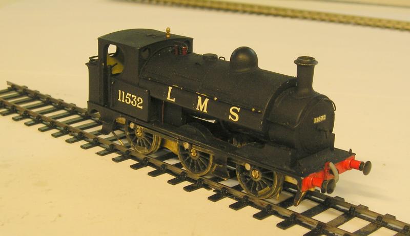
The model has a whitemetal body, which is good and milled brass chassis. Wheels are Markits and there's a quite nice metal geared GB. The model is not DCC ready so I hardwired a decoder. The model is akin to a kit built loco.
Running qualities, and this is my opinion, leave a lot to be desired. I found the loco waddled down the track and wouldn't run smoothly. First the center axle was supported by quite stiff spring and the driven axle by the gearbox. There are no bearings as such, so that was disappointing.
It was quite a long time ago that I attempted to modify the chassis for compensation and that sort of worked although I managed to break it - there's not a lot of material left after the hornguide slots are made.
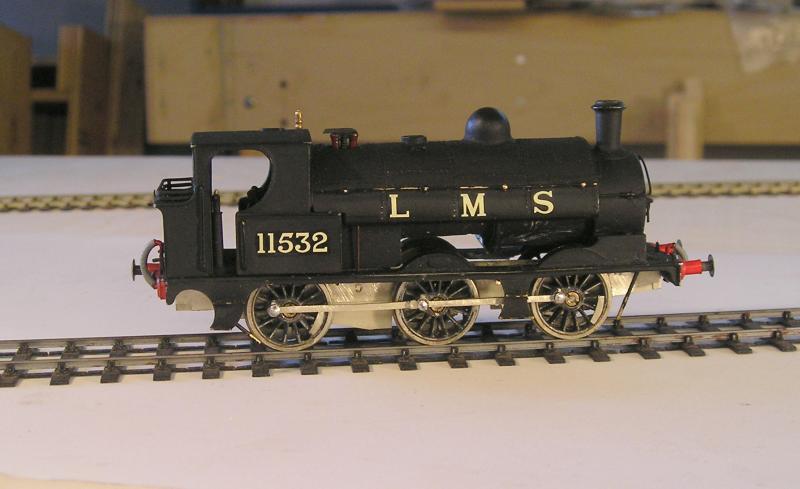
So, here's the loco as I left it:
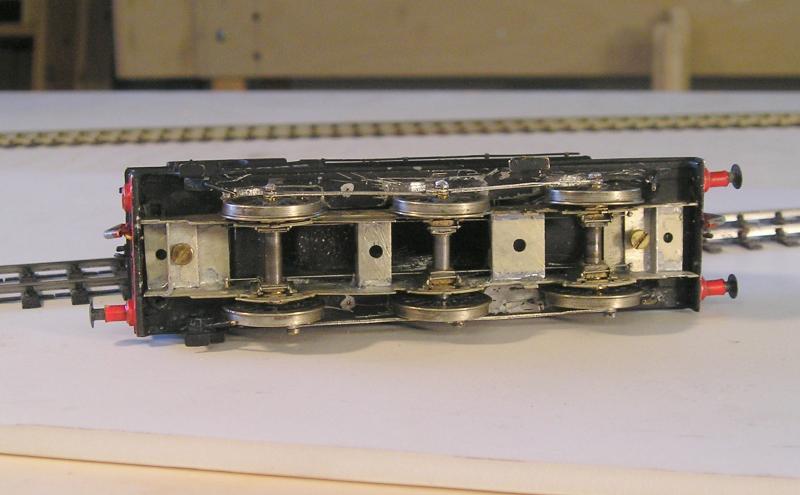
You can see below the compensated chassis that I made.
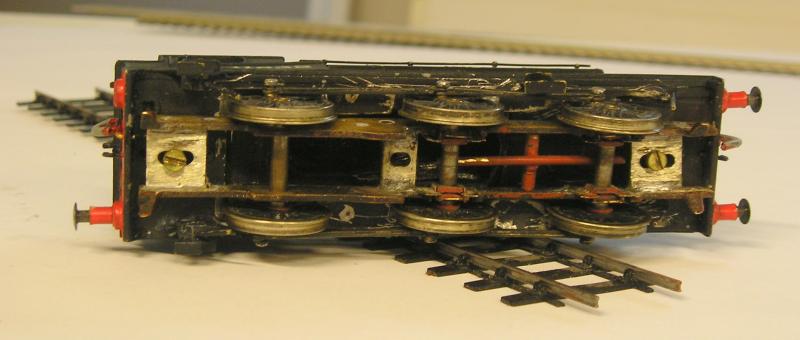
I decided that this chassis wouldn't do:
a) as I mentioned it is broken
b) the frames are way too think and there's isn't any detail.
c) I want to spring it using Continuous Spring Beam or CSB. Learn more here:
http://www.scalefour.org/forum/viewtopic.php?f=96&t=3605
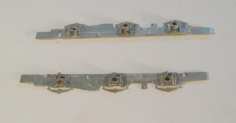
My solution was to obtain the chassis etch from London Road Models:
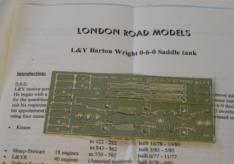
I was quite pleasantly surprised when I contacted LRM to request this and they agreed. I was warned that it is not a chassis kit, but that's OK for my purposes since I have the other bits from the original model. You'll note that there are coupling rods which is something you want on a chassis etch. These have quite clearly been etched to coincide with the bearing centers.
So, as I bring the Jinty together, I will start this.
My first job was to confirm that the wheel flanges are the right depth - they are.
Next I will prepare the frames to accept High Level CSB components.
John
 Last edit: by Brossard
John

Posted
Inactive Member
That LRM etch looks nice and clean plus they do some nice stuff.I see they have also brought out a 42 ft TT kit and well for smaller Pre grouping steam jobs.
Best of luck with the project.
Derek.
Posted
Full Member
I've been watching developments at LRM. There are some interesting wagon kits but I have more than enough in stock for now.
John
John
Posted

Full Member
'Petermac
Posted
Full Member
John
John
Posted
Full Member
First, the hornguides must be assembled and the hornblocks fettled to get a nice sliding fit. This is a very time consuming activity.

Having done that, the spring supports must be calculated. This is made easy by the use of a spreadsheet developed by CLAG:
http://www.clag.org.uk/
Variables are wheelbase and loco weight.
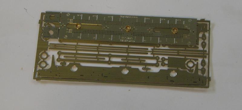
I removed the frames from the etch and discovered:
1) that the frames needed shortening by about 1mm to fit the body and
2) wheel bearing locations were not the same as the old chassis :hmm
The bearing holes needed opening which was hard work with a reamer.
Spring support holes were located using the very clever High Level jig:

Used thusly:
The above is the Cauliflower but the process is the same. The jig has holes to locate the corners of the hornguide cutout if necessary.
Next is to use the chassis jig to attach the hornguide/hornblock assemblies. In order to do this the coupling rods had to be made up. These are double thickness and I made them articulated. The rods are then used to determine the spacing of the bearing pins in the chassis jig.
The process is to leave one bearing rigid for now and to solder on the hornguides. Once these are done, make the cutout and solder on the final hornguide.
Today I soldered in the spring support pins which are medium handrail knobs. The spring wire was threaded through and secured at either end:
Notice that the hornguide/hornblock on the left is slimmer than the others. This gives me a fighting chance to fit a gearbox. As it happens the GB I plan to use is narrow enough, but it is a consideration.
Next job is to fit spacers and jig the chassis up.
John
John
Posted
Inactive Member
I like that springing arrangement.
Will study this further.
Oh,I guess those compact high level hornblocks would be best to use with 00 frames ?.Given the tighter clearances.
Cheers,
Derek.
Last edit: by shunter1
Posted
Full Member
John
John
Posted
Inactive Member
Oh Templot.Martin Wynne has released a vid on constructing a single slip drawing,Its fairly involved and remembering each step will take some study.
Cheers,
Derek.
Posted
Full Member
One of the skills I have yet to tick off is getting the hang of Templot.
John
John
Posted
Full Member
This morning I fitted axles by reaming the bearings ever so gently until the axles fell through the holes on their own.
I then attached the wheels and ran the chassis through the test point - very nice!
A dry fit of the rods using wire insulation to retain them temporarily confirmed that everything is good.
I then fixed the rods by soldering crank pin nuts on the crank pins, using a scrap of paper to ensure that I didn't solder everything solid. The paper also gives a good working clearance. Again a run through the test point was good - oooooh!
Lesson learned: you should only need to open the coupling rod holes to slightly more than the pin diameter (1mm). If you find you need to ream the holes heavily, as I did on my first Jinty chassis build, you know something's off.
I then test fitted the body:
The assembly fair whizzes through the point with nary a bump as it traverses the crossing - very chuffed with that. I'm not sure about those buffers - I may change them.
Here's a look at the spacers. I going to need to do some thinking about getting a Kadee on the back - long shank maybe.
The center axle moves too much and I think it would benefit from some thin washers. There are washers on the front and rear axles.
John
John
Posted
Inactive Member
Oh when you fit that Kadee could you show a similar photo as the bottom one so one gets an idea of how they are sorted.
Another question those 0.8 rivets you used for articulating the coupling rods were they Gibson jobs as I was thinking of trying that solution out.Medium or small I see advertised on Mainly Trains site.
Cheers,
Derek.
Posted
Full Member
There you go again with the rivet thing and coupling rods.
 These don't have rivets, just an overlap at the cosmetic joint. If you want to go to the trouble, I suppose riveted joints look better…marginally. You'll need three layer rods for that though. They obviously can't be seen when whizzing 'round.
I'll certainly show how I fit the Kadees when I get there.
I just spent some time fabricating guard irons and fixing them. I also put the brake hanger wires in. Had to reposition a spacer because it fouled the gearbox. :roll:
I will paint next.
Checking some photos, the buffers look accurate. They need repositioning to be straight though.
John
Last edit: by Brossard
John
Posted
Inactive Member
Do Kadee supply NEM pockets with the coupling.
Best of luck with progress,
Derek.
Posted
Full Member
I use #158 couplings for EM so don't bother with NEM. When I was working in 00 I used NEM a lot. I know Parkside Dundas sell the adapters but these would only be required for kits or really old RTR. For the pockets themselves, I bought a couple of packets of Bachmann T/L couplers just for these.
John
John
Posted
Full Member
The other problem I have now is that I can't get an 80:1 GB between the slim bearings, so I'll need to remove those and make the driven axle rigid. All fun and games.
So, I've ordered some gearboxes and motors from High Level today. Back on the shelf with this.
John
John
Posted
Full Member
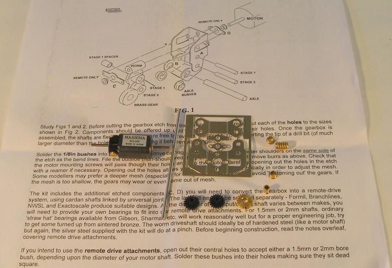
This is the Loadhauler Compact+ with a gear ratio of 80:1. I already reamed the 2mm holes to accept the shaft. Motor is Mashima 1224 with a 1.5mm shaft. When ordering gearboxes, be sure to specify the worm gear bore dia. The final drive gear is brass and will be fixed to the axle with Loctite 603.

This is the extender allowing more clearance between GB and cab in the case of driven rear axle, which I'm doing. My main reason for getting this is because the extender width is ~9mm and will go between the hornblocks in my chassis.
John
John
Posted
Full Member

The worm is fixed with Loctite 603 as are the shafts. I had it under power for a few minutes to work out any high spots. Running is smooth and quiet. The final drive gear is still loose, this won't be fixed until the very end because I won't be able to get it off after that.
I've had a quick look and there doesn't appear to be any problems getting things into the body. The drivestretcher will have to be angled so that the main gearbox frames clear the spring wires.
It's looking promising.
I didn't have to adjust any backlash, it was right from the get go.
Note that I've put the motor on sideways, with the fixing screws to the side instead of up and down. This will let me at least get the motor off, if I have to, with dismantling the whole GB.
John
John
Posted
Inactive Member
Cheers,
Derek.
Posted
Full Member
John
John
1 guest and 0 members have just viewed this.