Gladiator B16/1 A North Eastern Workhorse
Posted

Full Member
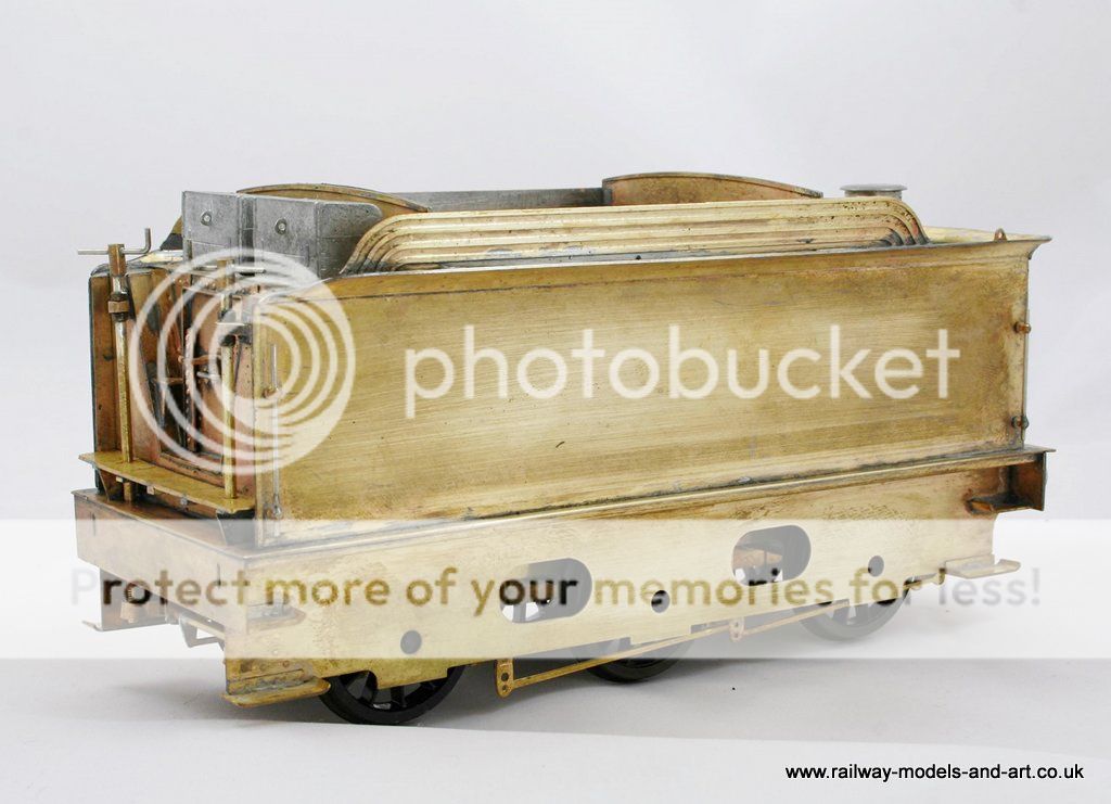
The completion of the build of a 7mm scale B16/1
[user=565]Brossard[/user] wrote:Hi John,IMO the smaller pieces should be added later, the large overlay is unlikely to come adrift.
I agree that the large overlay is unlikely to come adrift, I was just wondering about holding the small overlay in place. Having thought further while typing this I will do it as you suggest I think.
Regards Rob

Posted
Full Member
The original plan was to tin both sides and use the micro flame but I just couldn't get it to stick for some reason. The other issue was that despite my best efforts otherwise by bending them into all sorts of shapes the aluminium clips, bent the flares in places meaning some remedial work.

As you can see I still have some cleaning up to do, but I don't plan to clean up the inside of the flares until I have the tender top in place.
I am not sure whether it was me that got the overlay slightly out of line (it is wider than required so that you can file it back to get a crisp edge) or that the etched hole was slightly out of line but I will have to open the slot a bit to fit the rear lamp iron.
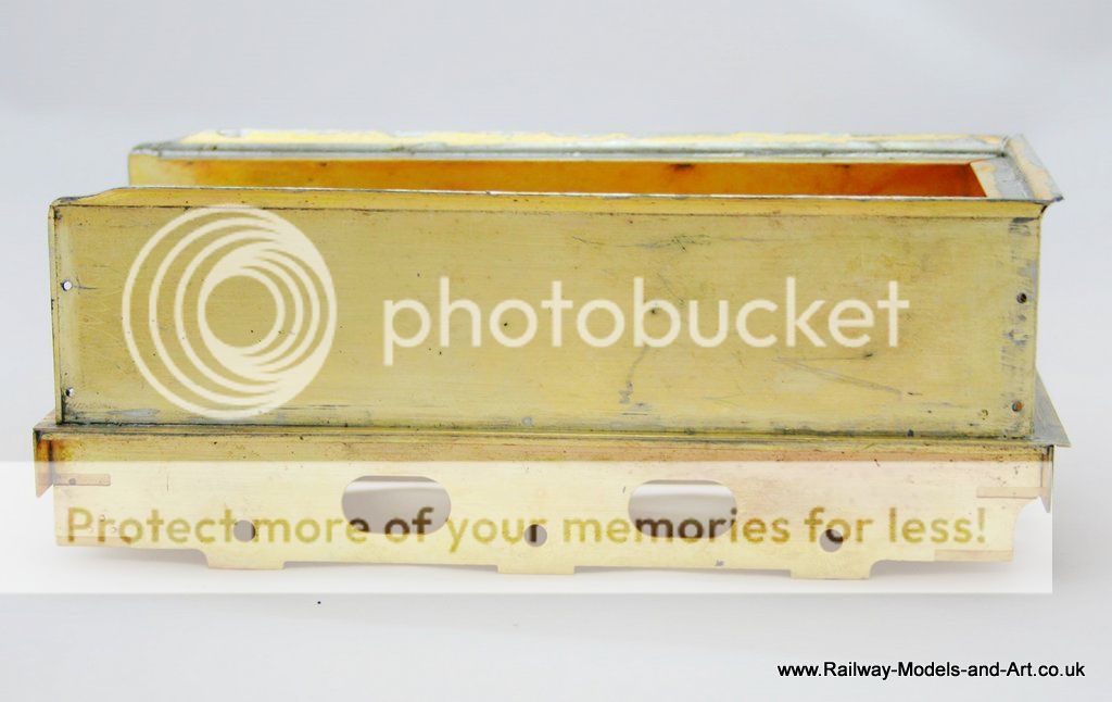
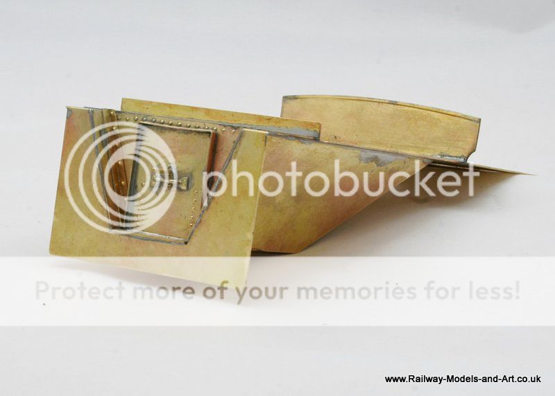
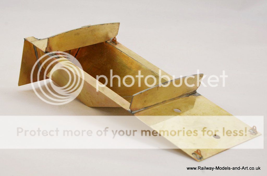
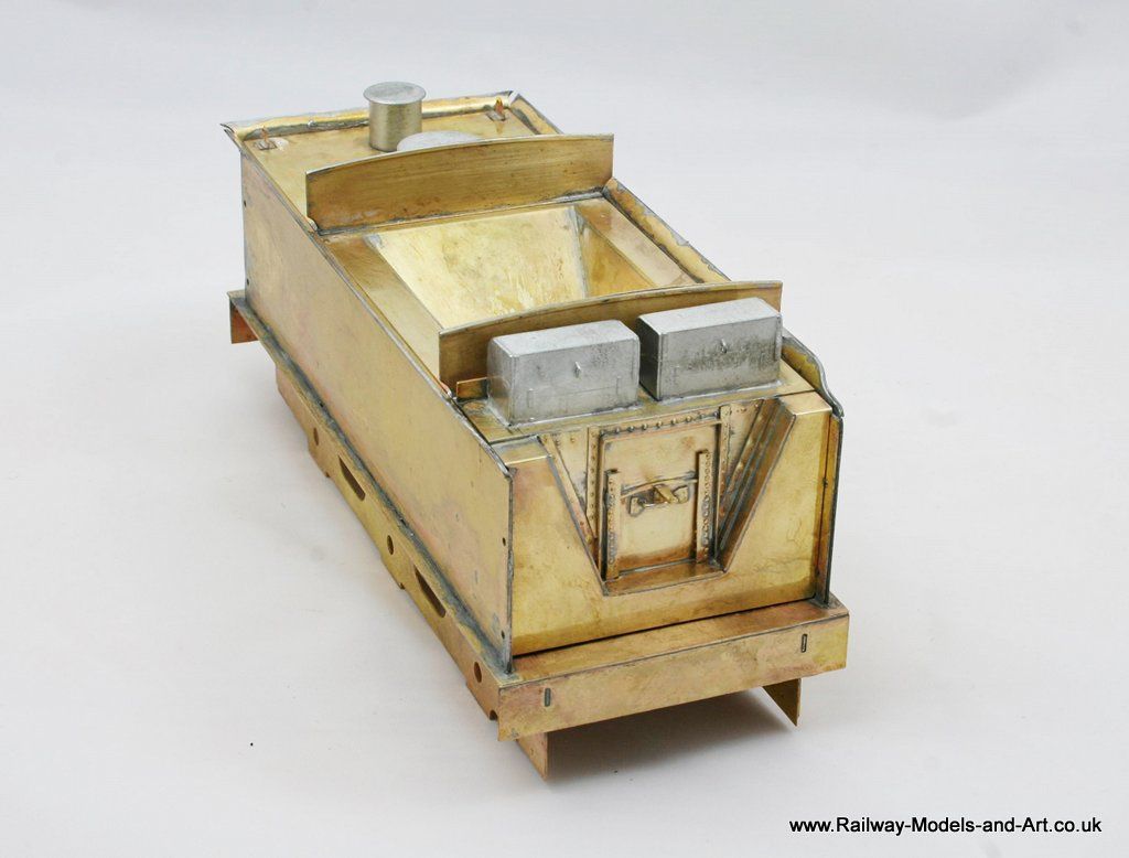
Next up I made a start on the tender top and coal chute. I want to get this fitted before attempting to make the corners of the tender flares from solder.
These all went pretty much as planned but there is a sight gap that I will need to fill. Again I am not sure whether it was my folding or the etch that's slightly out but it's an easy thing to sort.

I haven't done any cleaning up on this as I did it last thing last night and I was back to work this morning so couldn't be too late to bed. - The redness is from using the microflame to solder the seams. It washes of easily enough with some bar keepers friend.
Regards Rob
Posted
Full Member
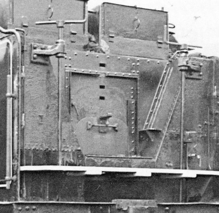
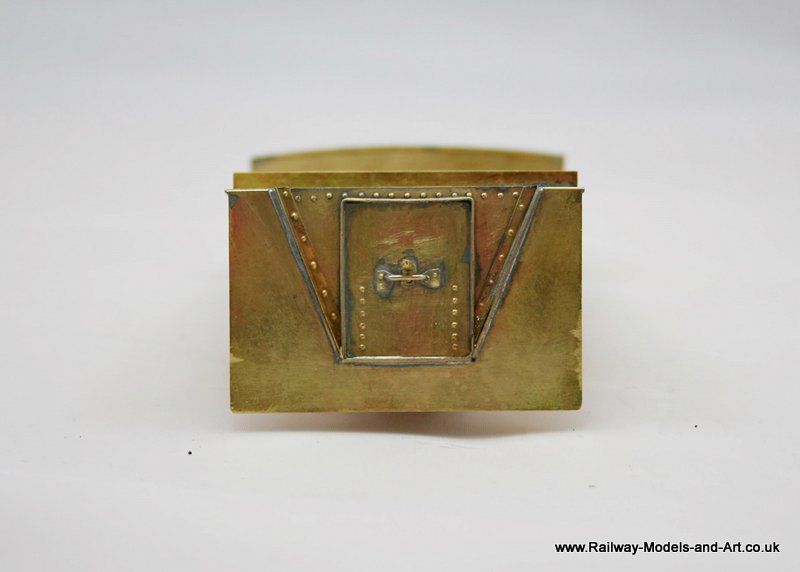
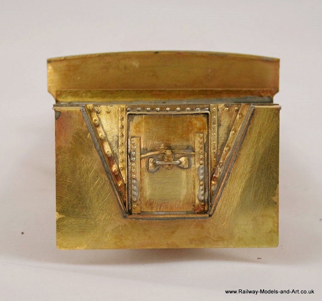
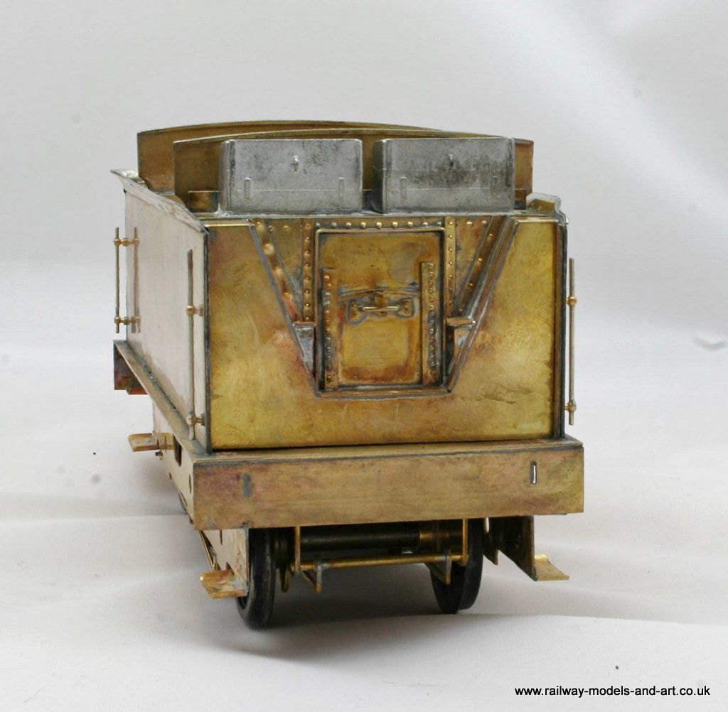
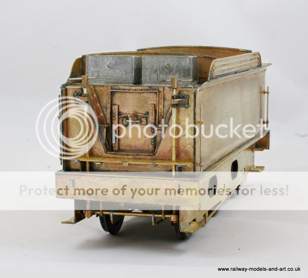
This is a cropped view of the tender front from the photo which differs a little from that portrayed in the kit.
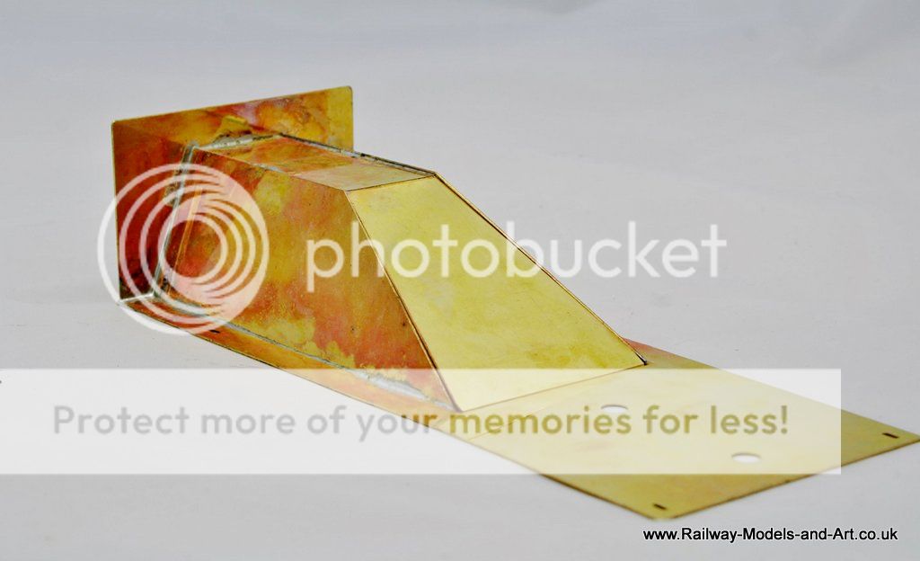
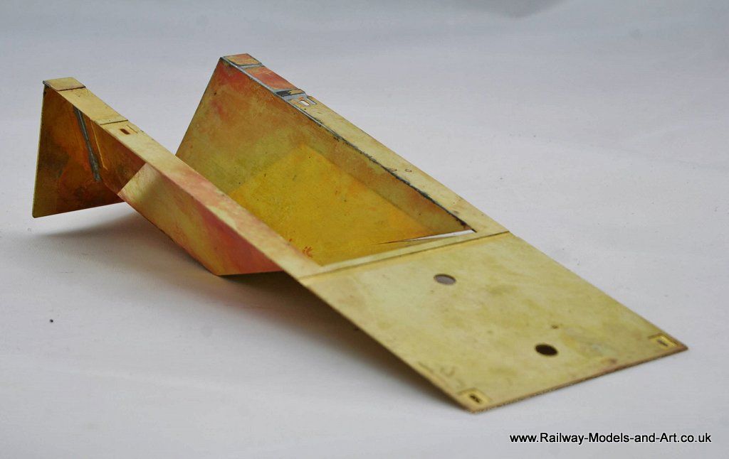
The kit provides a flattened V shaped plate with a rectangular cutout for the coal door and a coal door which is riveted and had two holes for a handle. The V shaped plate when fitted leaves long triangular gaps down either side of it.
There are some etched rivet strips provided to cover these and to replicate the angle plates that you see in the photo. I didn't find these (my fault for not looking at either the instructions or the etches before proceeding) before I had made up a couple of angle plates out of some half etched scrap that I had to hand.
having discovered them I still elected to use the ones that I made, because the rivet spacing was quite close together on the supplied strips. And it would have meant soldering two strips on instead of four.
I am sure the riveted strips will not be surplus for long.
The arrows on this repeat photo, shows what I have added to it so far. I still have a few bits to do - this sort of thing brings out the detailing devil in me I just can't help it.
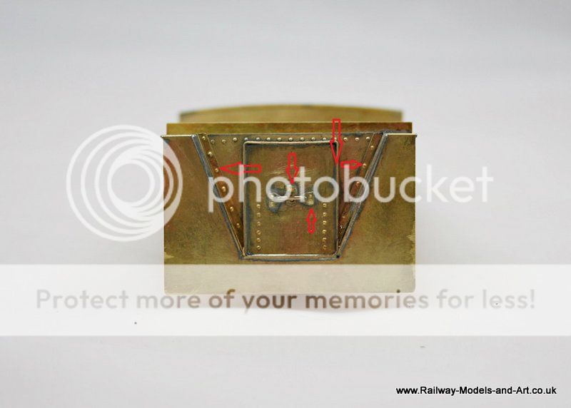
 Last edit: by Rob Pulham
Regards Rob
Posted
Legacy Member
Allan
Posted

Full Member
Chew away Allan :hmm
John
John
Posted
Full Member
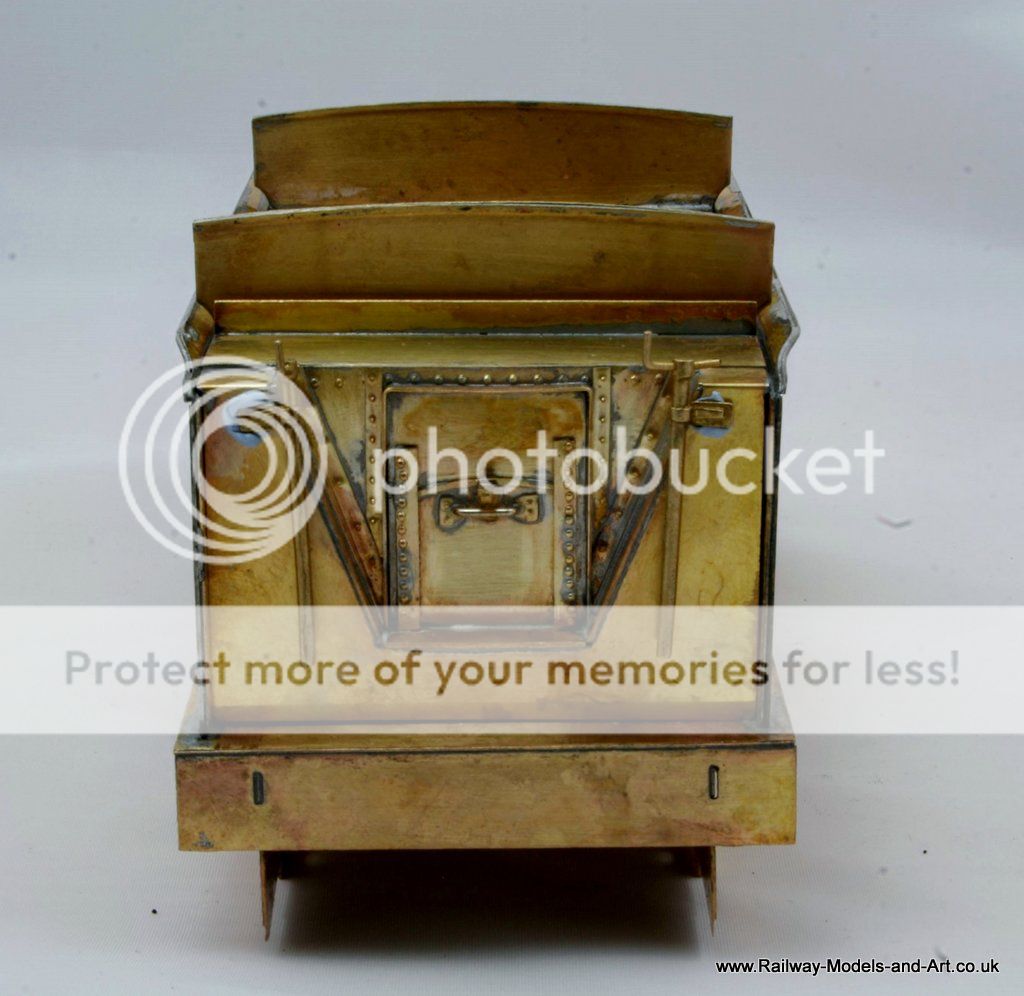
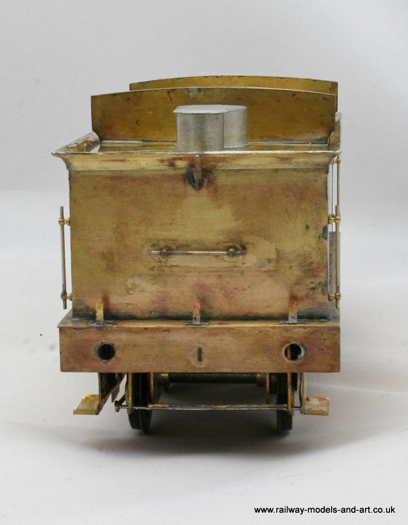
Following on from a comment about not being able get at the coal by Jim Snowden on the guild forum, further work was done last night to represent the sliding plate on the front of the coal chute.
Without taking the front back off and doing major surgery I had to employ a little subterfuge to give the impression of a sliding plate but I feel that once painted it will look the part.
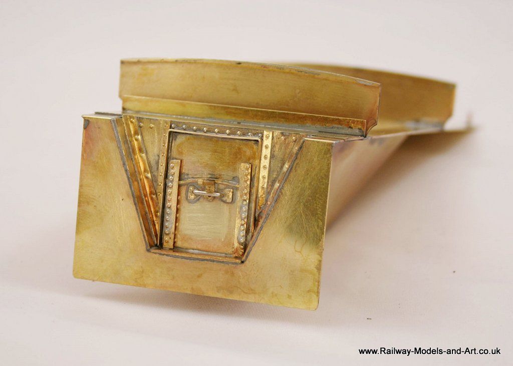
I also managed to get the front upper coal plate fitted and the lifting rings.
I still need to add the steps to the sides of the coal chute but that's about as far as I will go on this build (I keep forgetting "straight from the box"…) - I have lots of ideas for future builds of my own though.
Regards Rob
Posted
Full Member
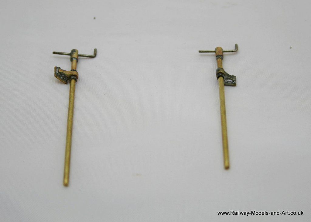
These are the castings provided.
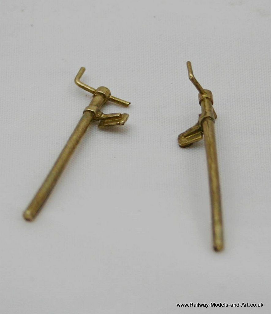
The problem came when testing them against the tender front (stuck in place temporarily with bluetac).
Despite my cutting them off the sprue with as much length as possible, they are short in the column length
I couldn't see any immediate way of extending the column* A better person than me might have been able cut it of and drill out the fixing brackets but they looked a bit on the fine side for me to be confident that I could achieve it
Now I have to be honest at this point and say that this really became a test exercise to see what I could achieve with my Proxxon mini pillar drill with the X-Y table attachment. I have been looking for something to try it out in anger, having only drilled out 4 buffer stocks since I got it at Christmas.
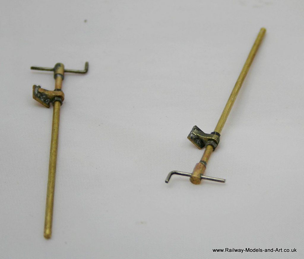
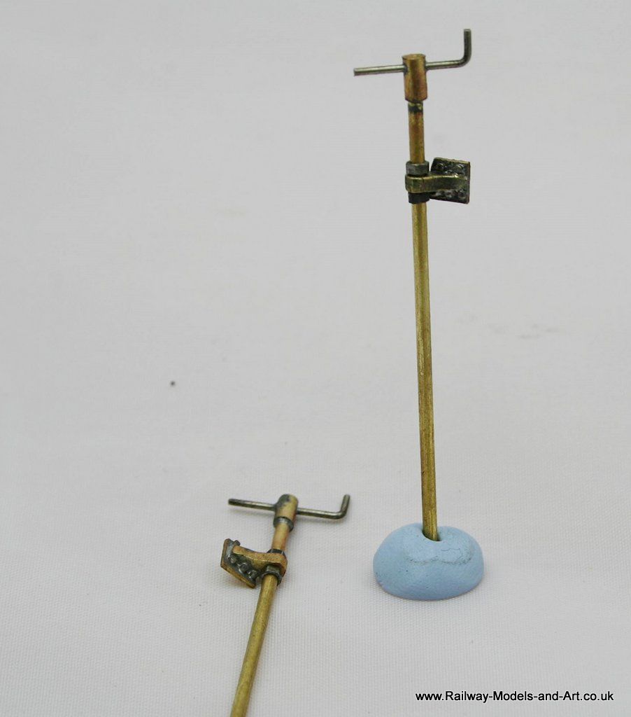
They took me all day to make but I really enjoyed it and I have parts roughed out to make a couple more for a build for myself at some point. to give an idea of scale/chunkiness the new columns are made from 1.6mm rod.
*Thinking about it afterwards I could possibly have joined an extension piece onto the castings where they go through the wooden floor extension that's shown on the photo of the tender front.
Regards Rob
Posted
Full Member
John
John
Posted
Full Member
I am aware of lot's of people having built the kit but I suspect that it was without the benefit of the photo of the tender front so they probably soldered them on lower down.
If I hadn't taken it as an opportunity to experiment with the drill press it could have a been a frustrating exercise. But in the end I really enjoyed the journey to get there and that's what does 'it' for me from a modelling perspective. It all depends on why you model.
Regards Rob
Posted
Full Member
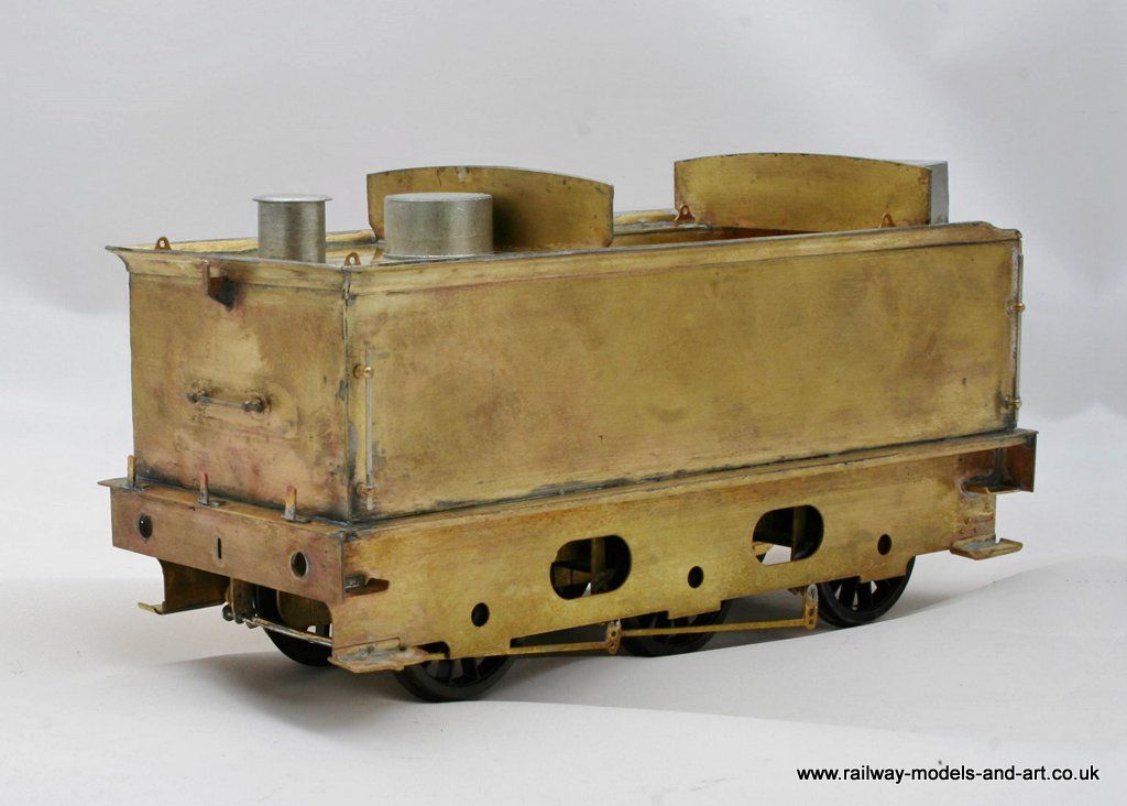
I managed to get all the whitemetal castings soldered on. I still haven't decided whether to fit the small steps at either side of the coal chute or not the jury is still out.
I haven't soldered the coal space/tender front in yet because I want to be able to get at the hand rails, lamp irons etc from the back before I do, then the last job will should be making the corners for the flares.

Regards Rob
Posted
Full Member
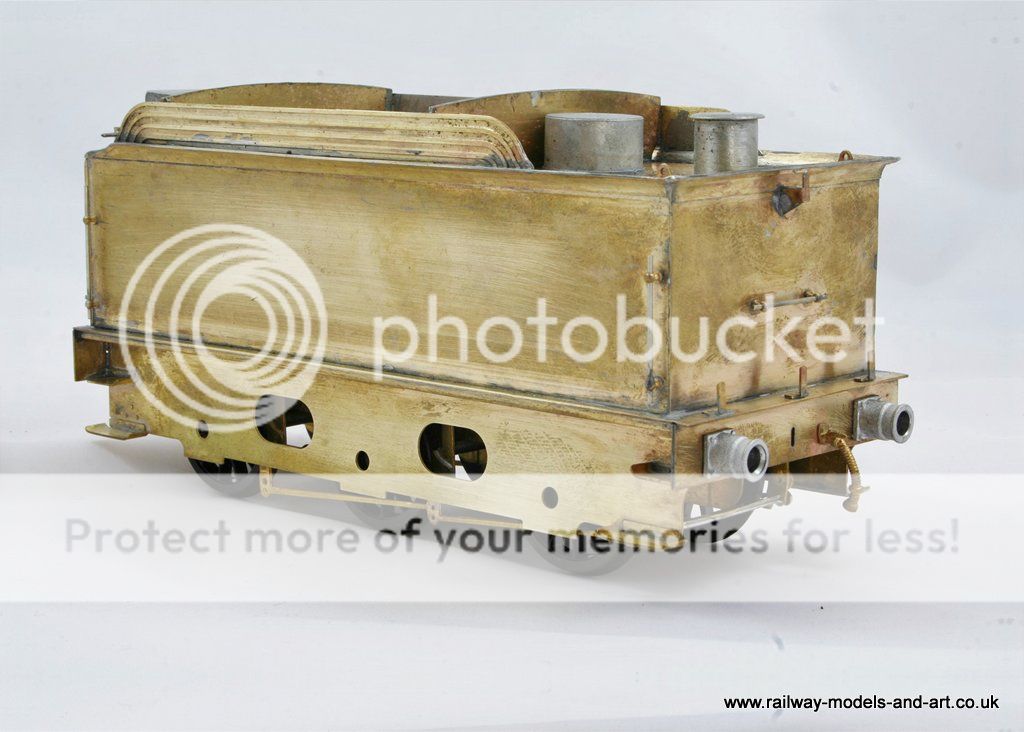
Still good progress has been made since then with most of the tender detailing cracked. I found that the rear tender flare overlay wasn't on straight to that had to come off and be straightened.
The coal space is still loose until I get the brake/water scoop standards in place - I figure it will be easier to drill the floor if it lifts out.
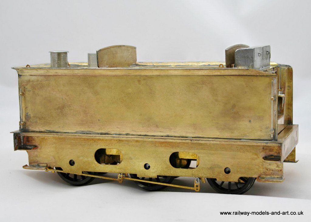
Note the longer hand rail at the front of the tender. This seems to have been a feature of a few of the B16 tenders and thankfully you can make it out on the one photo of 61450 that I have found to date.
The small steps were a bit of a fiddle but worth the effort I think.
Regards Rob
Posted
Full Member
The brake/water scoop standards rotate and you now need to unscrew them to get the chassis from the body.
When refitting the chassis during testing the cranks on the bottom of the shafts of the standards I realised that the brake rods were catching on the outer frame and had held one end of the chassi from fitting flat to the underside of the body. There is a plate with a slot in it in which two slots in the front ends of the inner chassis engage this was about 1.5 too high. To cure it I adjusted the offending brake spreaders and the rods inwards and then with the chassis upside down and engaged in the slots I used the microflame to run around the etches of the plate while pressing on the underside of the chassis with a block of wood. After a few moments the plate eased slowly downwards into the correct position and when the solder set again it was as it should have been.
As far as I can tell there is just the vacuum pipe and the axleboxes/spring castings to fit. I may also make the central 'buffer' from styrene but I will see how it goes when I test the running to see if it needs it.
Next it's on to detailing the chassis before tackling the body details.
Regards Rob
Posted
Full Member
When you say central buffer, do you mean the buffer between tender and loco? You could try using a cheesehead screw with the slot filled in and the head ground to shape.
John
John
Posted
Full Member
Yes that's the one but the reason that I am thinking of using styrene is that I am using the american method of pick up so I don't want a screw potentially creating shorts between the loco and tender. On the photo that I posted earlier of the tender front it's rectangular in shape so I if it's needed I would like to stick as close as I can to what's there having added the additional details to the tender front that I have. But thanks for the suggestion it's one I may well use on future builds.
Last edit: by Rob Pulham
Regards Rob
Posted
Full Member
John
John
Posted
Full Member
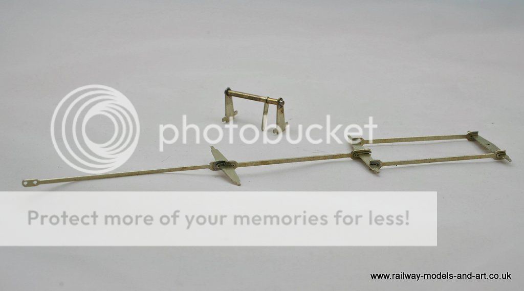
The instructions are along the lines of fit parts…. with a couple of build photos to assist with the general positioning.
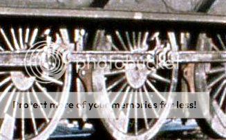
Thankfully looking at prototype pictures helped answer most questions. the first being how the hanger mounts fit
There is a better view in Yeadon but I found this and it saved me scanning the book.
As with some older kits, the forks in the etches for the rods connecting the brake spreaders are a little over etched so needed bushing.
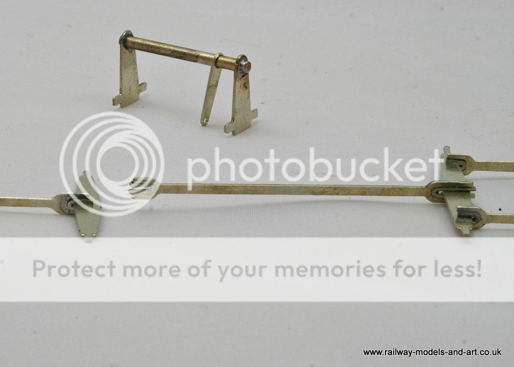
By accident or design some scrap from the chassis etches folded over the spreader was just the right thickness to fill the gap.
They just need soldering together once fitted.
Regards Rob
Posted
Legacy Member
I salute you sir !
Allan
Posted
Full Member

John
John
Posted
Legacy Member
Allan
Posted
Full Member
Each to their own I guess. John has put it far more eloquently and amusingly than I could manage though.
Regards Rob
1 guest and 0 members have just viewed this.