Deeley 0-6-4T "Flatiron"
Posted

Full Member
A restoration
Hi John,Looking very good - I liked the bogie bodge.
Nigel
©Nigel C. Phillips

Posted

Full Member
John
John
Posted
Full Member

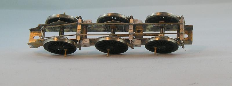
The components used for this are from Mainly Trains who do (or did, since they've ceased trading :sad:) these. The etches have Iain Rices' fingerprints on them. I'm more and more inclined to confirm the accuracy of parts by referring to the drawing. In this case, the brakes were spot on.
Brakes themselves are in three parts, body and inner/outer brake shoes- all soldered together. Care needs to be taken to get the cant of the shoes just so.
0.032" wire is soldered into holes drilled when the frames were being set up (difficult to get holes in line if you try to do this later). Brakes were the hung on the wires and soldered in place - roughly at this stage, but as close as possible.
Next I used a Loco Brake Rigging etch and the drawing to try to replicate the arrangement. I can see one joint has gone ahoo on the top left - tcchhh!. Easy to fix. All fiddly stuff.
Final stage is to fine tune the brake shoes. Obviously these can't touch the wheels, but in addition, the wheels need to come off easily. This means that the shoes will be more or less in line with the flange rim. I used a grinding wheel and file for this.
Looking at it, I'm at a loss as to how I'll get the wipers on - ah well - we'll git 'er dun.
John
John
Posted

Full Member
And by wipers I'm assuming you mean the strips of metal used to transfer electrical current from the wheels to the motor?
Fascinating as always.
I have a Dapol 45xx in pieces that I intend to rebuild one day… In N gauge!!!
Posted
Full Member
I've always liked this method, right from the first chassis I built (under the guiding hand of Iain Rice and his Loco Chassis book) - the Bachmann pannier tank. I've never trusted myself to do a rigid chassis (although with the jig I have that shouldn't be a problem).
Compensation is not that hard - you just have to set things up at the frame stage.
N gauge - ooooh! I've never worked in that scale - I'm going in the opposite direction.
John
John
Posted
Full Member
Posted
Full Member
John
John
Posted
Full Member
Wipers - this is where you recall plungers instead of wipers and where some strategic holes in the chassis opposite the rims would save the faff of trying to fit wipers and copper-clad among and between that very nice brake gear (and the gearbox). If space is getting tight under the chassis no reason why the wipers have to be there - there is always the top. Bit more inconvenient but they work just as well.
Nigel
©Nigel C. Phillips
Posted
Full Member
I usually try to have one side insulated and the other short to the frames - means only half to effort to install wipers. ;-)
John
John
Posted
Full Member


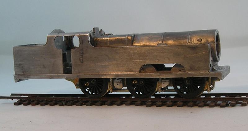
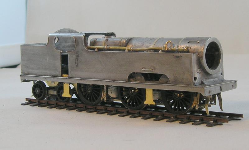
It's looking quite rough at the moment and I can see areas where I'll have to use filler. I used 70C solder to put this together - no worries at all. I set my iron to 300C. You can just make out where I filled some dirty great holes with solder. These locations are for handrails which should be 0.31mm NS wire. I also broke a rear footstep so will have to figure out how to mend that. The cast ones aren't that nice anyway.
That smokebox handrail has to go I think, the knobs are way too big.
I'm going to have to devise some way of putting the door handrails in.
John
John
Posted
Inactive Member
Posted
Full Member
The instructions you sent me came in handy Mick. Funny thing, I read through them a couple of times but couldn't find the step that says to join the two sides together. :roll:
John
John
Posted
Full Member

The stance looks decidedly off so I'll have to revisit that.
The rear of the chassis hooks over the bar behind the cab doors. I haven't a clue how to fix the front - maybe I'll just use glue :roll:.
John
John
Posted
Inactive Member
Posted
Full Member
Anyway, I double checked the ride height and it is correct by scaling the drawing. The photo is crooked I guess.
Next, I took a look at the buffer beams - yeccchhh! I thought (perhaps with hubris) that I can do better.
So, again, referring to drawings and photos I made these:
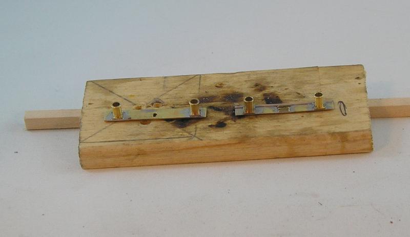
I started with some brass strip from my scrap box. Getting dimensions from the drawing, I drilled the buffer locations. Doing the vertical coupling slot is tedious.
Front beam is on the left and rear on the right. They are quite different with the rear having a beading strip (1mm PB strip) and a horizontal coupling slot. The support is L section brass strip.
Buffers are Alan Gibson sprung, standard LMS.
My plan is to use Archer rivet transfers to enhance the detail even further. I'll leave the rest of this towards the end and glue them on as an overlay.
John
 Last edit: by Brossard
John
Posted
Full Member
I've been bashing away at the body and the list of tasks seems endless. Still, I think I'm nearly there. I'll post some piccies at an appropriate point in the build.
John
John
Posted
Full Member
Progress is quite evident. Handrails have been installed. I've started the footsteps but the steps themselves need fitting. I scraped off the cast boiler bands and used masking tape to reinstate.
The pipe on top of the tank is 2mm brass tube with bits soldered on. The pipe on the real thing looked wonky as well.
You can see the bogie is on and I was wanting to see how the loco rides. I had to fit the bunker floor a couple of times before it began to look reasonable.

In this view you can see loops of NS wire for the cab handrails. What a faff that was!
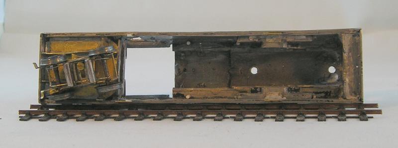
This view shows the brass bunker floor and frames for the bogie. It's only tacked at the moment. There's a nut (10BA I think) soldered to the back of the floor. The bogie has a slot so that it can pivot and slide. I also put in a spring. Again the choice of spring was a matter of trial and error. The frames were carved from brass sheet and fettled until the wheel flanges were happy.
I got a note from Colin at AGW Monday last to say that my order (including chimney, dome, safety valves and whistle) was being put together. Haven't heard from him since.
I've also requested a gearbox and motor from High Level since the one that was with this fouls the backhead (chopped out of a Mainline 2P)
John
John
Posted
Full Member
Wouldn't you know, today my box of goodies arrived from AGW so I now have most of the parts for this and two other locos. I still need the motor and gearbox from High Level.
John
John
Posted
Full Member
Fixing the front of the body. Couple of methods.
Tap a hole through the bottom of the smokebox, screw in a long bolt, so that the head and about and inch of thread are left, solder in place, remove head and use a nut and if necessary a washer to secure to the frame (solder in a support with a hole if there isn't one, looks like you have one though).
Drill and tap a largish piece of brass rod (or tap a brass tube with a thick wall), drill a hole in the bottom of the smokebox and solder in place. Use this to bolt the chassis to the body. This way you won't strip threads in white metal.
Solder a nut to the chassis, long bolt through the chimney.
If you haven't fixed the smoke box door, drill a hole from underneath, pass a bolt through with the head inside the smoke box. Solder in place. Nut (and washer) from underneath the frame carrier.
Nigel
©Nigel C. Phillips
Posted
Full Member
John
John
1 guest and 0 members have just viewed this.