More on Decoupling Magnets
Posted
#244497
(In Topic #13502)

Full Member
My Trials on magnet placement for Kadee Couplers
Hi,This subject has undoubtedly been covered to exhaustion but just for the record here are my experiments on magnet placement.
Magnet size
Smaller is clearly preferable, there are Youtube videos with larger (20 * 10* 2) magnets sitting under rails or bigger blocky ones outside rails but both these variants have their negatives.
I had some 10 * 5 * 2 Neodymium 52 grade (strongest) to hand so thought I'd try my luck with those first.
Location
One very useful tip from elsewhere was to offset magnets by 6mm - the forward distance between the trip pin ends.
Trials
As a test bed I used my favourite PVC substrate (surplus Venetian Blind Slats) 3mm thick, mineral filled and hence easily sculpted. I was able to cut rebates to adjust the height setting of the magnets, holding them in place with a temporary glue (note 1) to test.
I found a position with the magnet top 1.5mm below rail top worked very well, as in the photo
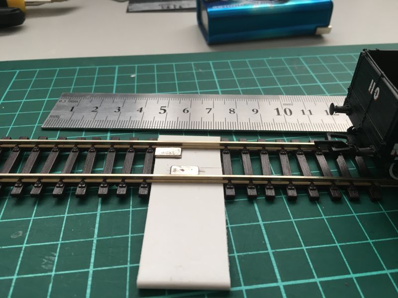
At 3mm the PVC is too thick for final end use but should not be a problem to find a suitable holder.
Colin
Note: Don't try superglue for the temporary gluing, it will rip the Nickel plating off the Neo magnet which is not something you want to happen.

Posted

Full Member
Not sure about small magnets being preferable. From a cosmetic viewpoint yes, from an operational viewpoint I think it could be questionable.
The actual operating distance you have looks to be less than 5mm. One of the reasons Kadee couplers are long is to allow delayed uncoupling, as well as a decent +/- leeway of where decoupling takes place.
The field of a Kadee magnet is designed to maximize lateral as opposed to vertical deflection. There are tight specifications regarding the distance between the decoupling arm and the magnet. I have so far been unable to find any reliable data of what the field is in these small magnets.
Steel versus brass axles makes a difference.
Rapido Trains do a nice small electromagnet if the concerns are purely cosmetic.
Nigel
©Nigel C. Phillips
Posted

Site staff
and that is why I use 3 rows of cube magnets on the D&S - a leeway to allow for uncoupling & delayed working.One of the reasons Kadee couplers are long is to allow delayed uncoupling, as well as a decent +/- leeway of where decoupling takes place.
Though looking at the photo by Colin, they are not Kadee but small tension lock couplings.
Ron
NCE DCC ; 00 scale UK outline.
NCE DCC ; 00 scale UK outline.
Posted
Full Member
Colin, so you see any drag from the axles? I experienced this a lot with UK stock, where the axles are usually steel. Especially with 8 wheel carriages.
Nigel
©Nigel C. Phillips
Posted
Full Member
Well spotted error, I had the wagon the wrong way around in the photo. Testing etc. was done with the Kadees.
Nigel,
I'll check for drag as you suggest.
I've some thoughts on the field shape but a bit more work required before addressing that point of yours. I need some iron filings, now where's my file?
Colin
Posted
Full Member
Firstly, Neodymium magnets are unlike your stereotypical bar magnet, they have their NS poles compressed together as I've done in this image, the bottom one has it's vertical axis compressed 10 fold. In reality it might be nearer 100 fold given the Neo is only 2mm thick. The alignment with magnet axis upright is as installed between tracks in my earlier post.
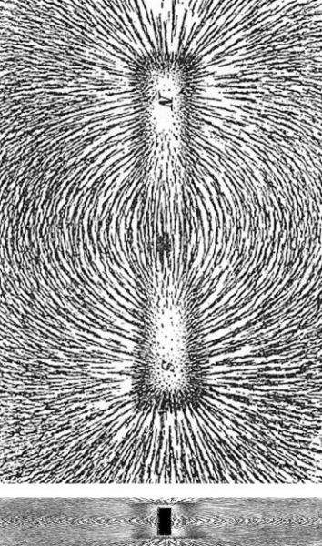
I imagined that the field would be splayed out almost flat as in the lower image, is this really the case?
These are above and side on views of the field for my two magnets with the old iron filings method. The twin fields tie in with my mental picture of a flattened field shape. The magnet offset creates two zones on opposite sides that help direct the trip pins to their respective sides, there being a clear zone of repulsion in between the two like poles.

The viewing window is just larger than track width and the magnet poles (same polarity) can be clearly seen.
One consequence of this highly compressed field is that there is very little attractive force if magnets are set just 1mm lower, uncoupling doesn't work! Hence I think axle attraction is not likely to be an issue.
The uncoupling range is just over the length of the magnet, 11-12mm, this may be ok for me in my confined goods yard. Will certainly call for fine shunting skills. Otherwise I'll need to move to 20mm long magnets and install beneath the track.
Colin
Posted
Full Member
That takes me back.
If you are using Kadee couplers (yes/no?) they are designed so that the curves at the bottom of the pins are symmetrical and overlap (if they do not they need adjusting), the intent being to look like a brake air line between stock. Having a magnet with a symmetrical fields with a null zone in the middle as opposed to two asymmetrical fields and a diagonal null zone would seem to be counterintuitive to the design. The trip pins need to move in opposite directions at the same time.
Again, if using Kadee couplers, the distance between the between the top of the between-tracks magnet and the bottom of the pins should be 1/64" /0.4mm. Anything over 0.75mm and they do not uncouple.
Even with DCC it can be fiddly getting couplers correctly positioned over a ~1 cm section of track. Ron's comment about having multiple magnets either side to able to use delayed decoupling is spot on - that's why Kadee magnets are around 5cm long.
Under track magnets solve the cosmetic issue.
Nigel
©Nigel C. Phillips
Posted

Legacy Member
Brian
OO gauge DCC ECOS Itrain 4 computer control system
Posted
Full Member
Brass rod 2mm diameter, straight pieces. Cut to size (HO, OO or EM) using originals as templates, slightly over long, grind pinpoints to length as required on the lathe, the wheel or the Dremel. "Model Engineering Brass Round Bar 2mm diameter x 500mm" ,£4.90, eBay UK. Mine came in 50mm lengths over here from eBay US. K&S here also have it.
Except on locomotives, where the mass minimizes magnet grabbing, all freight and passenger car stock here use brass or plastic axles, usually blackened.
I have said this several times before, the Kadee system is designed for HO standards, not OO.
Nigel
©Nigel C. Phillips
Posted
Legacy Member
Brian
OO gauge DCC ECOS Itrain 4 computer control system
Posted
Full Member
You can of course just add a full load of lead sheet or 4 steel 1/2" nuts. That will add some mass and inertia.
Nigel
©Nigel C. Phillips
Posted
Site staff
I weighted my wagons up using the NMRA standards using sheet lead and while one van may move by itself once uncoupled, with a couple or three together, they don't move. And I found the brass wheels from Bachmann still have steel axles - go figure that out !Hi Brian,Nigel
You can of course just add a full load of lead sheet or 4 steel 1/2" nuts. That will add some mass and inertia.
Nigel
I could use these STEAM ERA MODELS - Wheels
which have brass axles suitable for Bachmann & Hornby
Ron
NCE DCC ; 00 scale UK outline.
NCE DCC ; 00 scale UK outline.
Posted

Full Member
For what it is worth, I carried out similar experiments - including using iron filings on a test track! I got my physics teachers involved - they understood the physics, not the couplers! In the end I went for 20mm x 10mm neo magnets, under the track. Parallel, but opposite poles against each other. I use a piece of sponge as a "brake" which negates the metal wheels and axels and have added a weight, which greatly assists the uncoupling. You can run all sorts of tests, but if there isn't weight in the wagons, the tests are pretty worthless.
So far they have worked fine. Yes, it takes a bit of practice to uncouple consistently, but I think I will build that into my operating sessions and have it as some sort of scoring system. It didn't take long to get better at it and definitely added something to the freight operations. Will have to think of something similar for the passengers. If I am going prototypical (which isn't really my way) I will have a passenger timetable to run with no locos - it is 60s Southern region after all!
There is loads of great advice here specifically about Kadee conversions and magnets, so be sure to check it out. It saved me hours of pointless experiments!
Regards
Michael
Posted
Full Member
All your, Sol's and now Headmaster's feedback has been most helpful and informative. I've been trying to address a specific problem in two locations where I'm not going to rip up fully installed work to install under track decoupling, so was looking for a track insert solution. So what is optimal seems like it won't be possible.
Yes, I'm using Kadees, and as far as I can see straight out of packet they're close to specification WRT height above the top of rail. What is interesting is the alignment of the trip pins as shown in this photo, pulling on top, pushing below. Both angled, the latter by nearly 45 degrees to track line. Wagons are weighted up to near NMRA specs
The Neo must have a more powerful field as my magnet is 1.4mm below rail and the tip 0.8mm above.
The Bachmann wagons have steel axles but no drag is evident, the field shape I have may at least fix this issue.
Finally I agree with your comment about the magnet offset being counter-intuitive, I'll go back and check with no offset and compare operations.
Thanks again,
Colin
 Last edit: by Colin W
Posted
Full Member
Hi Michael,….. In the end I went for 20mm x 10mm neo magnets, under the track. Parallel, but opposite poles against each other. …….
Regards
Michael
I can't picture the magnet positioning you describe as the Neos have their poles on the large flat surfaces which in most cases I've seen are then installed flat (as I have done). In my case same poles are facing up for both magnets,
Colin
Last edit: by Colin W
Posted
Full Member
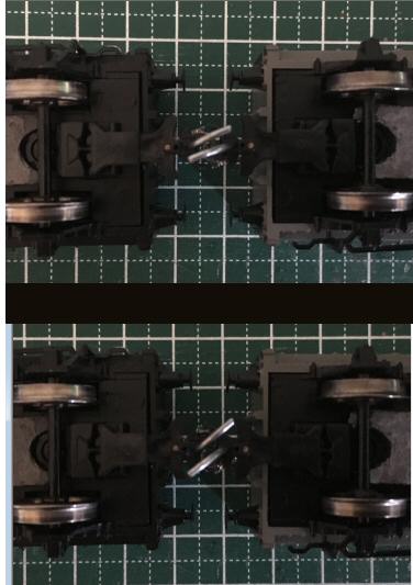
When the magnets are directly opposite each other the leading pin being ahead of the other by 6mm is drawn first to its magnet. As the coupling is still linked, this pulls the trailing pin in the wrong direction, away from its magnet.
When the magnets are staggered by the same amount as the linear separation of the pins then the pins separate in their required directions at the same time.
All this would suggest that the best orientation of under track magnets is to offset by the 6mm factor but angled slightly to ensure the fields are aligned with the track axis as per Nigel's point.
Colin
Posted
Full Member
Neo magnets have different power ratings. You can tell the power by the N rating (I mistakenly thought this was Newtons - a measurement of force - but it isn't. However it is a measurement of the power of the magnet.) Comparisons between different systems is pretty meaningless without this measurement.
My magnets are north on one side and south on the other (remember they measure 20x10mm. The magnets attract on their broadest surfaces, not on their edges.) So, on one side of the track, North faces up, and on the other south faces up. (I didn't realise this was important until I read a number of threads here and then understood why sometimes my test system worked and sometimes it didn't.)
I have not found the need to stagger magnets at all, and maybe this is a pole issue. Or it is the magnets. Or it is luck. I use buildings to indicate where the magnets are (there are a variety of methods for doing this described on this site) and have found the 20mm magnets to be ideal for giving a suitable uncoupling range. Others swear by rows of 5 x 3mm cubic magnets. I will admit I had mixed results, but better modellers than me had them working consistently, and I am not going to argue with them!
The weight of the wagon being uncoupled is also crucial - there is a NMRA standard for this in America which Kadees follow. British rolling stock is much lighter. Again, comparisons between systems is meaningless if this is not a standard.
Obviously, at the end of the day, whatever works for each of us is ideal, but there really needs to be some standardisation if we are going to compare different systems. Good luck with yours and I look forward to seeing how it progresses
Regards
Michael
Posted
Full Member
Re-reading the thread, I can see our difference is that you have both magnets with the same pole facing up (let us say north) whereas I have one magnet with north facing up, and one with south facing up. I have to fix them one at a time or the they will jump up and connect. Maybe this is why we are having different test results?
Regards
Michael
Posted
Site staff
Ron
NCE DCC ; 00 scale UK outline.
NCE DCC ; 00 scale UK outline.
Posted
Full Member
I was desperately trying to find that here.
Colin
1 guest and 0 members have just viewed this.