More on Decoupling Magnets
Posted

Full Member
My Trials on magnet placement for Kadee Couplers
Michael raises an important point - the orientation of the magnet. Discs seem to be vertical, cubes will be vertical or horizontal depending on which way they are laid, bars can be vertical or horizontal, usually horizontal. Cubes would seem to be the most problematic.N = Neo = MGOe. apexmagnets.com has some really useful information that will help in optimizing the force (may it always be with you).
Metal ramps were common from the advent of AWS, modern era has them everywhere, so an over-the-sleepers magnet looks OK with with a bit of weathering or some yellow.
Nigel
©Nigel C. Phillips

Posted

Full Member
The big plus for PUMS in a retro fitting situation is that existing ballast can be extracted and replaced by the magnets with far less visual impact than my flat magnet method (that BTW uncouples just as well with no axle attraction).
I've still some 20 * 10 * 2mm Neos on their way from China for under track installation in all the locations in my Goods Sidings which remain un-ballasted / loosely fixed down. No more "Cans of Worms" will be opened, promise!
Thanks to everyone for helpful input,
Colin
Posted
Full Member
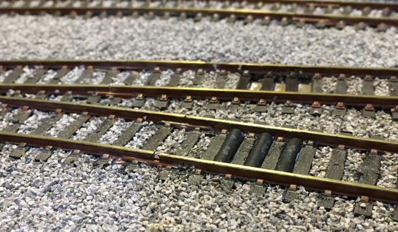
I had on hand 100 small disc Neo magnets, 3mm diameter and ~1mm thick. 12 of these end to end were inserted into a 14mm length of black PVC heat shrink tube (Φ 2.5/1.25) which takes the discs snuggly. A tiny plug of Blutac at each end tamped in to prevent escape, the whole assembly fits between sleepers. Three rows of these as per the prototype work very well.
Being smaller than the 3mm cubes and I suspect less powerful, I don't get any axle drag of note but 100% success in both push and pull modes thru the uncoupling zone. Pull mode requires a full stop of course but a slow push will uncouple on the fly and the uncoupled rake can be gently pushed forward in delayed uncoupling mode. Most impressive! Thanks again Sol.
Colin
 Last edit: by Colin W
Posted

Site staff
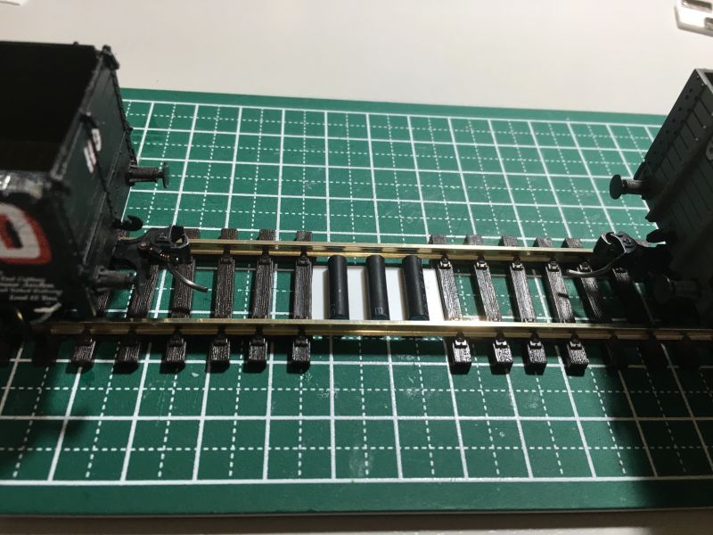
Can you get a photo two please?
I replaced sleepers with the row of magnets & I guess your method could also replace sleepers.
I have never seen Kadees uncouple even pushing without stopping and backing up a small bit to allow the hook parts of the knuckles to separate to allow for the delayed setting.
Ron
NCE DCC ; 00 scale UK outline.
NCE DCC ; 00 scale UK outline.
Posted
Full Member
I think the only way it can uncouple on the fly is with axle drag from the magnet. Doesn't do that with brass axles.Then again I use Kadee magnets that seem to have lateral rather than vertical magnetic fields. Although if you stacked the circular magnets that is what you probably have.
Hope you didn't heat shrink the heat shrink.
Nigel
©Nigel C. Phillips
Posted
Full Member
good points and questions,
- The tubes are about 1mm below rail height so about 1.7mm above tops of sleepers. That was the best height I found by trial and error.
- Disc magnets are stacked then laid sideways so magnetic field is tangential to the track as per PUMS
- great idea to replace the sleepers now I've got it working, should have thought about that.
- Heat Shrink was not shrunk, that's going to kill magnets if overdone. Could even be fire risk with Neos. Hence Blutak plugs on ends to hold in place. Laid with fields aligned (all Norths same end), the little magnets had a habit of being repelled out of their tubes by the adjacent field.
- I'll try video of the uncoupling, so far it's been careful "handomatic" operations as they were tested on loose track in my study. Now they're installed I'll hook up a loco and report back.
- As mentioned I can't see any obvious drag pulling axles over the uncoupling zone. I had seen it before with other larger magnets but not these small ones
Colin
Posted

Full Member
Michael
Posted
Full Member
Credit must go in part to excellent tips I picked up here about using a paint brush with shortened bristles to spread, level and settle ballast. I extended that to using a tiny paint brush, given the same shortening, to do the fine distribution. Pity my earlier work isn't of quite the same standard!
Colin
Posted
Full Member
That looks good. You can always paint the covers with grey, black and off white dots to look like ballast, or even give it a thin coat of ballast.
Nigel
©Nigel C. Phillips
Posted
Full Member
Note scenic work in this area is at a very early stage, only ballasting done with any level of completeness
[yt]tTdkE1CuBdE[/yt]
I'm going to have one more try with my larger magnets in line with track (where all this started) but with opposing poles up on the opposite sides of the track as per Headmaster's advice.
Colin
Last edit: by Colin W
Posted
Full Member
I like the glowing firebox - very neat!
Michael
Last edit: by Headmaster
Posted
Full Member
To sumarise the key features:
- A solution for Kadee uncoupling if track and ballast have already been laid
- Three rows of 3mm * 1mm disc magnets assembled in heat shrink tubes, magnets all aligned in same direction. Tube OD 3.5mm - (do not heat shrink, plug the ends with blutak)
- A support base of 24 * 14 * 0.5mm PS sheet to place the magnets' top edges 0.8mm below rail tops
- Tube spacing - to mimic removed sleepers
Assembly tips:
- Tape the cut PS base to the underside of a piece of track, locate in line and between rails
- Beneath this, tape two slab magnets 1 under each rail opposite poles up. This will help keep the tube magnets in situ while gluing. Otherwise they have a nasty habit of jumping out onto the adjacent tube, superglue and all!
- dab tiny specks of CA superglue onto the PS sheet between sleepers and insert magnets one at a time ensuring poles are all in the same direction #. They are drawn to the magnets beneath so fix quickly
To remove existing ballast
I first softened it by applying a concentrated solution from those "bubble blowing" packs. This contains glycerol, detergent and water, I let mine concentrate for a while by evaporation ( not essential) before applying with a dropper. This viscous mix doesn't spread too far beyond the treated area and hangs around for long enough to soften the hard PVA glue. Leave 1 day. The end result is easy to scoop out as a gritty paste.
Colin
Posted
Full Member
Will you be adding sleepers to extend outside the rails?
Regards
Michael
Posted
Full Member
since I'm cutting out existing sleepers after removing the ballast, the outer sections will be left as they are.
I'll use under track magnets for new installations.
Colin
Last edit: by Colin W
Posted
Full Member
Colin
Re-reading the thread, I can see our difference is that you have both magnets with the same pole facing up (let us say north) whereas I have one magnet with north facing up, and one with south facing up. I have to fix them one at a time or the they will jump up and connect. Maybe this is why we are having different test results?
Regards
Michael
Hi Michael,
At that time I was experimenting playing around, then settled on a "between the sleepers" solution for my already laid track so never came back to address the points you raised. As you are now working on a new layout, my follow up may be of interest.
1) You are correct, under-rail magnets work best with N one side, South t'other.
2) To stagger or not to stagger - ….. I've done further work and can now see where the stagger configuration makes an improvement. In needs some detailed explanation.
To uncouple the leading wagon is being pushed forward, its trailing uncoupling pin lies to the left of centre (looking face on). Under compression this pin is pulled by the magnet as far as the coupling jaws will allow.
Once the loco stops and pulls back the jaws spring apart and remain so as long as over the magnets.
In practice the uncoupled loco / wagons will pull back beyond the magnet zone and on advancing again the leading pin needs to deflect fully open again to get the uncoupled push effect.
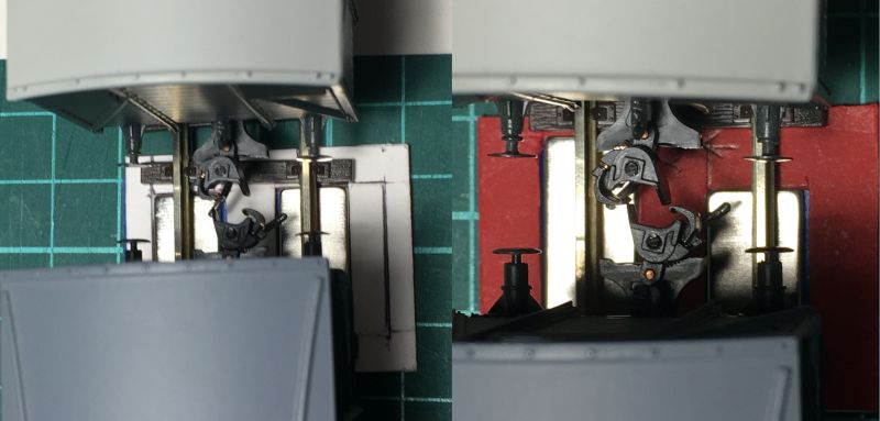
These two photos show how a staggered magnet setting (5mm) allows for better opening of the advancing wagon's coupling jaw. Motion is from top to bottom. With only 20mm of magnet length there is little margin for error and with aligned magnets the approaching jaw may not open fully in time IF the other wagon is well forward in the magnet zone.
If you can position perfectly then there would be no need for the staggering but I found it helps during the second stage of the uncoupling process.
Last edit: by Colin W
Posted
Full Member
Posted
Full Member
************************************************
Hard to believe it's nearly two years since I settled on an uncoupling solution for my established layout. With my already ballasted track, I used a variant of the methods described here by Perry and Sol, rows of small magnets aligned across the track, in my case replacing sleepers (see posts #26, #30).
They worked well but noticeably caused some drag on wagons that were underweight or had substantial steel weights in the bodywork.
Most solutions which I've read / watched aim to replicate the Kadee type uncouplers, installed either above or below track. Whichever, there are convincing Youtube videos that an axle rolled over of these devices is "grabbed" in its magnetic field. Why?
The underlying assumption in these designs is that Magnetic Poles need to be separated across the tracks, North one side, South the other as with the Kadee devices. This gives a tangential magnetic field which does the uncoupling, pulling the arms to each side. It also creates the powerful field perfectly aligned with the axles.
It seemed to me that there is no need for the poles to be aligned this way. If all North Poles were facing "UP" on both sides of the track, there would be no transverse magnetic field BUT there would be a strong attractive field locally around each top face (pole). Would this be enough to effect uncoupling if the magnets were correctly positioned?
My trials today suggests a solution is possible. The lateral attractive uncoupling force is, as predicted, not as strong as with poles opposed but strong enough to work reliably in my trials so far. The tips of the two coupler ends are angled enough to each side (see post #35) to reach into the localised magnetic fields. Axle drag is greatly reduced.
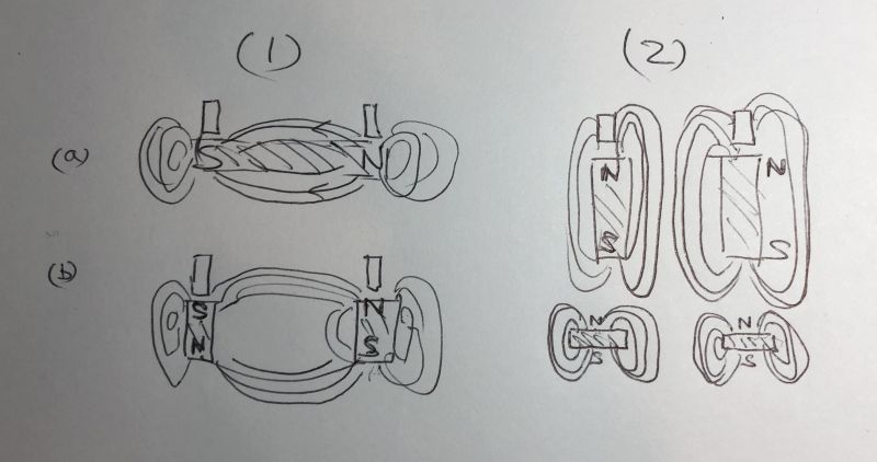
This rough sketch shows the difference: 1(a) the Kadee uncoupler style and rows of cubes between sleepers 1(b) local under rail magnets, poles opposed design
Type 2 shows designs where all Norths are up, 2(a) vertical columns of magnets 2(b) flat thin Neo magnets Poles aligned
Last edit: by Colin W
Posted
Site staff
Even Bachmann Brass wheels still use iron/steel for the axles, not brass !!!
Ron
NCE DCC ; 00 scale UK outline.
NCE DCC ; 00 scale UK outline.
Posted
Full Member
Interesting because when I was researching this issue on Youtube there is a guy with 200+ Modelling posts and 28,000+ followers who has stumbled across the same solution as mine, AFAIK while not realising why!
His video "The inconvenient truth about Kadee Uncoupling" is USA based and he demonstrates the axle drag issue using his Athern stock. from feedback he seems to be considered a connoisseur regarding the stock on his layout. He notes that axles and iron weighting both give problems.
It's been raised before but swapping out many axles and various embedded iron weights is not a practical solution for me.
You either have to configure your opposed magnetic poles and adjust your choice of strength to minimise the problem or find another way. Hopefully with more work I can find a working solution with matching poles. In my case it may be easier as I'm using Code 75 track with thinner rails and sleepers, thereby reducing the gap between magnet and dropper. Other options I'm exploring include intensifying/shaping the field as per the Kadee undertrack device.
Last edit: by Colin W
Posted
Full Member
As mentioned previously, having matched poles under both rails avoids much of the problem with axle drag. Sourcing reliable magnets proved more difficult.
My limited supply of strong magnets was not going to be enough for Upper Hembury and a new purchase off Fleabay could not pull proverbial skin off rice pud! So resorting to recycled ex HDD magnets I've reworked my configurations.
These are POWERFUL! I had to have them set well down below the rails (details later) and offset to be mostly outside the line of the rails thus:
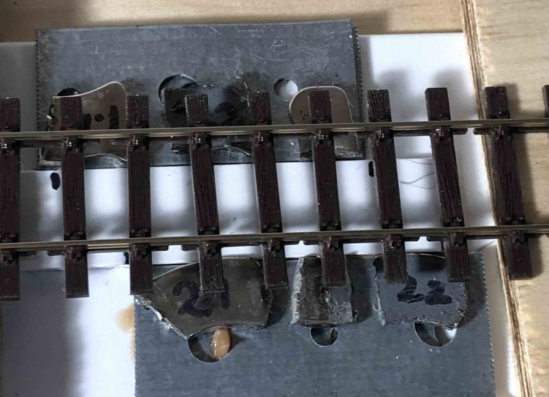
The view is oblique so the magnets appear to be off-centre - the inner edges in fact are directly under their respective rails.
With my usual offset of the two sides (top 10mm to left of bottom) I get a 50mm coupling zone that works very well and very little noticeable axle drag. Quick video to demonstrate.
[yt]T9ho03Dj2tQ[/yt]
1 guest and 0 members have just viewed this.