Ecos 2 question
Posted
#111297
(In Topic #5826)
Guest user
In the instructions it says i can use railcom with it if i change cv 29 and 28
now with the switchpilot wired to the programming track i read cv 29 as 128 which is correct to documentation.
Now it says i have to set cv 29 bit3 and write a value of 6 into cv28
The confusion bit for cv 29 do i just put 3 in the write window and press the write button and on cv28 do i write 6 and press the write button ?
There are 8 boxes below the write window to do with bits should i be using that somehow.
Brian
Posted
Inactive Member

Les
Devon Junction
Kernow Junction
Kernow Junction

Posted
Guest user
Brian
Posted

Full Member
Pete
Regards
Pete.
ECOS2 with RR&Co Traincontroller and a load of other electronics so i can sit back and watch the trains go by.
Pete.
ECOS2 with RR&Co Traincontroller and a load of other electronics so i can sit back and watch the trains go by.
Posted
Guest user
I must admit this writing bits is a bit confusing cant get me head round how you know what bit you are writing to
Brian
Posted
Full Member
Regards
Pete.
ECOS2 with RR&Co Traincontroller and a load of other electronics so i can sit back and watch the trains go by.
Pete.
ECOS2 with RR&Co Traincontroller and a load of other electronics so i can sit back and watch the trains go by.
Posted
Guest user
I read that if you enabled railcom on the switchpilot you could do any programming of it on the main so i thinks thats a good idea then it says about changing cv 29 cv 28 and im thinking how the hell do you know what bit you are changing as you only have the write window there and them 8 tick boxes underneath this bit programming is a bit confusing
Brian
Posted
Guest user
If you don't want to use the bit method write 136 into CV29
To arrive at that - in the manual page 29
CV29 - only bit 3 and bit 7 are used
Bit 7 is fixed and read only and has a value of 128
Bit 3 is 0 (Railcom off) or 8 to activate Railcom
So 128 + 8 = 136
Put 136 in the Value box and Write it
For the bit method
on the right of the 8 boxes it says: Bit [7..0]
Bit 7 is on the extreme left, Bit 0 is the extreme right
Bit 3 is the 5th box from the left
It might help to understand the bits/boxes if you put 128 in the Value box DO NOT WRITE it
use the + key to increase the value to 136
you will see the binary adding up in the boxes
CV28 just needs 6 in the Value box
Apologies if I am teaching you to suck eggs
Chris
Posted
Guest user
Your certainly not teaching someone to suck eggs
Basic cv`s numbers etc i grasp and do
But when it started mentioning bits etc i was in area i dont know what im doing here
I dont pretend i know things when i dont i would rather ask thats how we all learn.
At some point i may ask you to do a bit of a tutorial on doing the bits in cv`s so dumbos like me can grasp and understand it instead of avoiding doing it like im sure many do rather than say i havent got a clue.
Im sure many dcc users if they are honest dont know how to do it,
many thanks
Brian
Posted
Guest user
Certainly be able to do a tutorial of some sort.
I need to get a bit more familiar with uploading so I can add graphics possibly.
Chris
Posted
Full Member
Having spent much of my life designing electronics and computerised machines I easily fall into the trap of forgetting that not everyone is familiar with the terms "bit", "byte", etc - I could go on.
The idea of a tutorial to at least discuss the relevant computing terms used in cv programming is a great one and if I can be of any help, I will gladly join in. I did spend some of my early career teaching technical staff about bits and bytes. Maybe some of that work could still be relevant in this context?
Posted
Guest user
Perhaps a tutorial is something we can work together if it felt it would be of benefit to others.
Chris
Posted
Guest user
Many rightly suggest using the pl10W motors as they draw less current but i have not got any of those so its the standard pl10 at the moment i haved used and old laptop supply to power it i have found it fires the motors fine but i do need to allow a rough 2 second delay before refiring otherwise a misfire occurs,
So it seems succesfull so far
Brian
Posted
Guest user
I set the ECoS Duration on the Accessory Edit Panel to 33ms (the minimum)
The SwP CV3 - 6 are set to 2, you may need 3 for 00 but I haven't tested on other than N Gauge.
If the ECoS pulse is too long, after the SwP has fired the motor it reads the instruction again then fires the motor again.
Mine fire as fast as I can keep touching the screen with no heating up of the coils. I also use PECO Power-Lube (PL-64) rather than a "normal" thin oil to lubricate before installing.
Chris
Posted
Guest user
The pl10w`s are far better to use certainly with a switchpilot and really better with any dcc accesory decoder something that is not advertised enough by the industry or in the modelling community.
I have got loads of pl10`s so i try to use them not ideal but they work.
My next experiment with this switchpilot is i have a crossover track which acts as a reversing loop it has a pair of points i have a Masterswitch plus laying around so i may try and fire the pair together through that on output 4.
I dont think i can use the reversing feature on the masterswitch as i dont think its solid state contacts so it would short the Ecos. But i will just buy another one of those Psx units that i used on the 009 layout section that works fine.
Brian
Posted
Guest user
I agree, also the PL10W's are built to a better standard than the original PL10's were in the last century and perform very well in my opinion.
The pl10w`s are far better to use certainly with a switchpilot and really better with any dcc accesory decoder something that is not advertised enough by the industry or in the modelling community.
But I always have had good service from PECO point motors.
I have a PL10 I use as test unit with SwP and that works again on N with the same settings as the PL10W.I have got loads of pl10`s so i try to use them not ideal but they work.
My power source for the SwP is a 15v 5Amp AC transformer which offload gives 18v (the AC input limit for the SwP).
I haven't tried a MasterSwitch but if it has a reversing feature I would have thought the contacts are Break before Make so there shouldn't be a short situation. Try it, the ECoS will just trip out so no harm done providing you have tested that track with short test first.My next experiment with this switchpilot is i have a crossover track which acts as a reversing loop it has a pair of points i have a Masterswitch plus laying around so i may try and fire the pair together through that on output 4.
I dont think i can use the reversing feature on the masterswitch as i dont think its solid state contacts so it would short the Ecos. But i will just buy another one of those Psx units that i used on the 009 layout section that works fine.
Chris
Posted
Guest user
This is a product i bought a long tme ago along with 4 v2 masterswitches which i have never got to work properly i know some people have had good results but i have noticed there are quite a few that have not i think part of the problem is the claims of using virtually any power supply within reason are wrong as over a period of time it was found an old laptop supply was the best thing to use with these things.
So i think now the masterswitches i have will now go in the waste of time box after wasting to much time in the past and this afternoon trying to use them.
So change of tack what i will do now with the output from the switchpilot.
Brian
Posted
Guest user
I have an idea that might work for you.
Could you let me have sight of a track sketch.
May be able to rig up a test as I am waiting for some stuff to come.
Chris
Posted
Guest user
I can of course use another output to do the switching if i wanted to which is an option of course.
There is a new actual trackplan drawing just uploaded the other day in my layout thread but here is a rough sketch of the situation
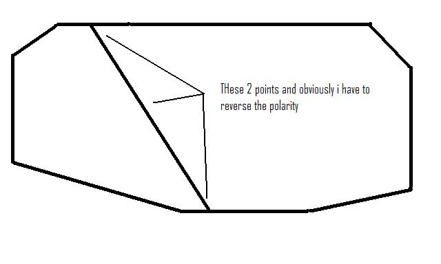
Hope that is clear enough
Brian
Posted
Full Member
When setting routes from RR&Co, I have included a 500mS delay between points and this seems to be plenty to get the CDU to recharge. The only time I have found any problem is when I get a bit impatient and start up more than one route change at a time in different areas of the layout. The CDU still often manages, but sometimes the odd point doesn't throw due to there being no power available. Still, with my interlocked signals everywhere, I can quickly see that I need to hit the offending point, or route, again.
In one case of a crossover, I have used a single peco motor with wire in tube connecting it to the two points involved. That also works well.
1 guest and 0 members have just viewed this.