DCC Signalling.
Posted
#109889
(In Topic #5761)

Full Member
Signalling with an ECOS and LDT LS-DEC_NS Signal Decoders
Do you ever have a day when you start something and wish you never started well i have had one of those but there was light at the end of the tunnel or should i say along the track.In my capacity as Brian's (Henryparrots) test engineer my next project was to fit light signalling to Stonebridge and eventually operate it via Traincontroller (TC), however for those who do not use TC don't worry there will be none of it here i do another bit for the gang later.
OK the plan was use my ECOS2 to operate my Eckon signals via a dedicated interface made by LDT in Germany. These are popular items and can be bought ready made or as a kit which is considerably cheaper (BrianPR1 ears just pricked up). These boards will work with Lenz, ECOS and quite a few others they are not just for ECOS.
Unfortunately LDT do not make a bespoke UK interface so you have to opt for the NS option which is prototypically Dutch operation. (cheers for that Matt)
There some great advantages to the board:
1. you don't need resistors for the Led's the board has them
2. Power for the led's can come from your controller or seperate 14 - 18vac PSU.
Time for the piccy the board.
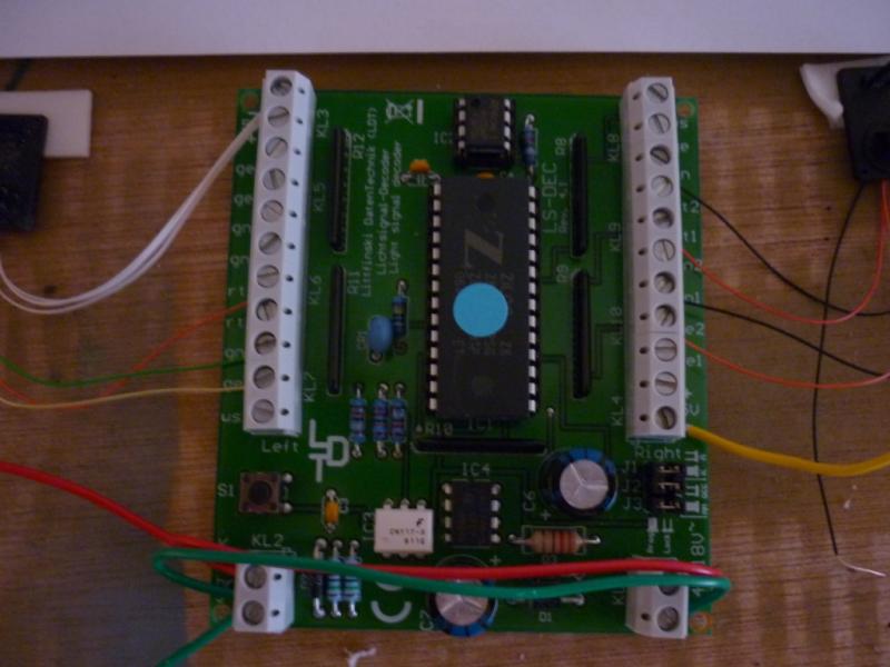
For the project i decided to use a 3 aspect signal and two 2 aspect signals for testing and demonstrating purposes. For obvious reasons i did the testing on top of the board (and boy am i glad i did!)
Wiring the signals to the board is straight forward and the downloadable connection diagrams are clear just have your readers handy.
The test bed
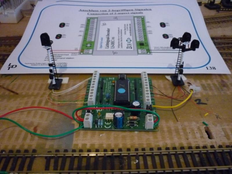
In stis instance all my power was coming off the track bus and linked over to the optional power input (red and green wires above)
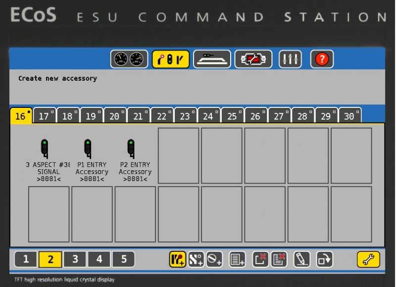
So thats me wired up now for the ECOS, In the ECOS there are options to set up prototypical signalling very graphically via the touch screen needless to say it is easy when you know how so in the accessory section i set up my signals and set a decoder address of 30, if you have experience of using Lenz LS150 decoders the LDT programs in a similar way i.e set your first address and the next follow concurrently (in theory)
Setting up my 3 aspect signal on the ECOS

And all three signals setup and ready to go by touching them to change their aspects
Next job is to power up and program the board. This is where my day went pear shaped could i ellers like get the thing to program, after a lot of playing around and a quick check on another forum i finally sussed it. On the board there are three jumper links. Link two is either on or off depending on what DCC system, despite what the manual says!!! link 2 must be off for the ECOS. Once i got over that hurdle the rest was straight forward unfortunately i can only use addresses 1-4 and 5-8 i need to explore more deeper.
You can use the same dcc addresses as your point motors so your signals can be interlocked etc. i do not have enough knowledge to that yet.
I shall try to post a video later but here is a teaser

Comments good or bad most welcome.
Regards
Pete
 Last edit: by wogga
Regards
Pete.
ECOS2 with RR&Co Traincontroller and a load of other electronics so i can sit back and watch the trains go by.
Pete.
ECOS2 with RR&Co Traincontroller and a load of other electronics so i can sit back and watch the trains go by.

Posted
Guest user
The Ldt signal board how many signals or lights can the board handle and can each switching point take more than 1 led at a time for exxample if say when a signal turns red could the opposing one turn green by default off the same switch point?
What is NS?
Brian
Posted
Full Member
I don;t think the board has that intelligence to control two signals but if you bodge two leds into one contact you get volt drop so they will both dim.
PEte
Regards
Pete.
ECOS2 with RR&Co Traincontroller and a load of other electronics so i can sit back and watch the trains go by.
Pete.
ECOS2 with RR&Co Traincontroller and a load of other electronics so i can sit back and watch the trains go by.
Posted
Guest user
Is what Geoff is doing in the thread below simila to what the LDT board does or is it a totally differant thing?
http://yourmodelrailway.net/view_topic.php?id=7782&forum_id=9
Brian
Posted
Full Member
The LDT is a simpler solution where basically each signal set is allocated one or two dcc addresses which will switch manually on the ECOS when you tap the screen.
But what you can do is interlock the signals with the point position similar to what Geoff is doing. The LDT can share the same DCC address as your point motors so it should be able to set up that if a point is in a certain position the paralled signal will show red or green as appropiate. Which i think the pros call interlocking. Linking the signals to a point is do able with LDT's and most DCC without a PC operation.
Unfortunately i know jack doodoo about signal operation other than what i pick up on here and even that goes over my head
Anyway here is the link to the video.
http://www.youtube.com/watch?v=H_07iaooopU
Last edit: by wogga
Regards
Pete.
ECOS2 with RR&Co Traincontroller and a load of other electronics so i can sit back and watch the trains go by.
Pete.
ECOS2 with RR&Co Traincontroller and a load of other electronics so i can sit back and watch the trains go by.
Posted
Guest user
i think it will be simple to hook them up with TC:roll: at least if you get them to work with the ECOS it will be easier to make the cross over.
Posted
Full Member
Two reasons why I have gone for a bespoke solution - actually 3 I think -
The first is so that I can have interlocked and operational signals even with TC not running.
The second is that due to the complexity of the junction, it is not a question of interlocking one signal with one point, but of interlocking a signal with a complete and clear route. I am sure this can be done with TC, but it will certainly be involved and of course also requires TC to operate the signals, whereas mine operate automatically (at least I hope they will when it is finished) when the route has been set and is unoccupied.
The third, less important reason, is to ensure the signals only operate when the points have really moved - or at least the switches that change frog polarity have operated. This should avoid any problems occuring when a point has been told to operate but for some reason has not moved across - just like the real thing, I think.
Anyway I am still very interested to follow your progress Pete. I have a large layout and may want to do things differently in other areas.
Posted
Full Member
An update on the decoder programming its very straight forward really if the destructions were better!..hey ho.
First off all each decoder must be addressed in a block sequence of eight addresses i.e 1-8, 9-16, 17-24… and so on.
The board is basically in two halfs so when you address the board you input two addresses e.g if i was allocating addresses 17 - 24 to the LDT i first fire in 17 then press the onboard programming button and fire in the second 21, just like setting up an LS150. The addresses the remainder outputs in sequence.
If you connecting 4 x 3 aspect signals it will use all eight addresses i.e 17,18 for sig 1. 19,20 for sig 2 etc.
As i came to setup my second board today again it wouldn't program but now i am fully experienced i progammed default 1-4 and 5-8 first, then i was free to change them as i wished. Wehther my two left the factory without defaults settings by mistake i don't know. But what i do know is that putting the defaults in first kind of "booted up" the board to life.
Now we are ready to fit preprogrammed.
Regards
Pete
Regards
Pete.
ECOS2 with RR&Co Traincontroller and a load of other electronics so i can sit back and watch the trains go by.
Pete.
ECOS2 with RR&Co Traincontroller and a load of other electronics so i can sit back and watch the trains go by.
Posted
Guest user
As always, I'm struggling to keep up with the vast amount of information and news on here, but any item labelled signalling catches my eye.
That is a lot of useful information about the LDT signal decoder, it inspired me to have another look at the ECoS symbols and try a few 3 aspect variants.
Posted
Full Member
I set up points and of course i used it to set up the signals for the demo its then over to TC.
You are right i must make more of it. As for setting routes you say press the pushbutton? so on the ECOS track plan you have the option for pushbuttons like TC.
I must take time and learn the thing and make more use of decoder programming as well:oops::oops::oops:
Regards
Pete
Regards
Pete.
ECOS2 with RR&Co Traincontroller and a load of other electronics so i can sit back and watch the trains go by.
Pete.
ECOS2 with RR&Co Traincontroller and a load of other electronics so i can sit back and watch the trains go by.
Posted
Guest user
Posted
Full Member
No you right Brian i should get the ECOS setup correctly so i shall follow your lead and there is no rush, the deadline is the bacon butty from me at the Preston Show!
Rgds
Pete
Regards
Pete.
ECOS2 with RR&Co Traincontroller and a load of other electronics so i can sit back and watch the trains go by.
Pete.
ECOS2 with RR&Co Traincontroller and a load of other electronics so i can sit back and watch the trains go by.
Posted
Guest user
Posted
Full Member
Cheers for that i have to print it to read properly and i will work through that this week.
Oh i have sussed "programming on main" not to sure how but it works.
Regards
Pete
Regards
Pete.
ECOS2 with RR&Co Traincontroller and a load of other electronics so i can sit back and watch the trains go by.
Pete.
ECOS2 with RR&Co Traincontroller and a load of other electronics so i can sit back and watch the trains go by.
Posted
Full Member
Block signals on the main line:
This is where I really come unstuck with the ECoS/LDT combo with no mods or additions. I'm assuming current sensing detectors in each block, the longest train must fit in the shortest block, and a steam hauled train with no resistive axles, so the coaches are not detected. It's an easy matter to set up 3 aspect signalling around a continuous run: a train in block 1 approaches signal 1 at green, as it passes and enters block 2 the s88 contact 2 changes the signal to red, when the train enters block 4 ahead it will be clear of block 2, the signal 1 changes to yellow, enter block 5 ahead and the signal returns to green. Each aspect of one signal is triggered from a different s88 contact, so each signal needs three "routes" but these overlap, e.g. the route triggered by contact 5 will set signal 1 to green, signal 2 to yellow and signal 4 to red.
The problems start with the ECoS/LDT setup when there is a train behind which passes signal 1 showing yellow. The signal changes to red when this train enters block 2. Then the first train enters block 5, which clears signal 1 to green even though the second train is still passing it. There does not seem to be any practical and cost effective way of preventing this with the LDT, all I can suggest is to instruct the drivers never to pass a yellow on the main line.
What an excellent account, Brian. When I started to get excited about RR&Co a year ago, I thought I would move away from my ZTC511 and thought ECoS would be the way to go. The only thing that put me off, so I haven't moved at all yet, was that it seemed that there would be tremendous overlap and redundancy with both RR&Co and the ECoS. Your account strengthens that arguement for me. It would seem that with an ECoS controlling the layout, only a relatively simple software solution is necessary to automate train movements. Similarly, with the full version of RR&Co, only a relatively simple controller is needed. I don't think either combination is currently available?
Anyway, back to your thorough account. As you know I am quite into signalling at the moment, so am particularly interested by your description of how you would operate block signals with the ECoS and LDT unit. Is it possible to include within the ECoS set up an "AND" function. This would then allow some additional logic so that instead of occupancy of block 5 clearing signal 1 to green, that detector would be "ANDed" with an absence of occupancy in block 2. (i.e. Block 5 AND NOT Block 2 equals Signal 1 green).
The Heathcote hardware units which I have started using do something like this in a very clever way. Each block has a unit which provides both detection (using infrared) and drive for a 2,3 or 4 aspect signal. The units are daisy chained together with a single wire. Each unit sends an ac frequency down this wire to the unit before it. If there are no trains present on the track this frequency is an "all clear".
When the first unit is passed, it turns its signal red and waits for the incoming frequency from the next unit down the chain to change. When the next unit is passed, it turns its signal to red and then after detection is over - i.e. the train as fully passed the detector - it sends the yellow frequency up the line to the first unit. Moving on, when the third unit detects the train, it sends yellow to the second which now sends green or double yellow back to the first.
If a second train passes the first signal at yellow, then that unit puts it signal back to red and waits again for the yellow frequency.
It is a very neat solution. The units include override inputs to allow for points in between or any other logic to intervene. I have included a whole heap of logic at my junction and it all seems to work together well. These units can be combined with current detection devices rather than using the built in infrared, so that signal control could be managed mostly by hardware with the interface to the DCC controller and software being mostly just for detection, perhaps just with some simple accessory decoder outputs to force the signals to red if the controller/software required it.
This would be a very different solution for signal control to the LDT unit.
Last edit: by Geoff R
Posted
Guest user
Posted
Guest user
Posted
Guest user
1 guest and 0 members have just viewed this.