D C C Wiring
Posted

Banned
Everything live even when using insulated joiners??
The plan Kevin is referring to is the one I posted here :http://yourmodelrailway.net/view_topic.php?id=13081&forum_id=21#p231943
It works fine on Industry Lane… :thumbs

Posted

Site staff
Nothing to do with switching the frog, as it ain't got that far.
Ed
Posted

Legacy Member
Kevin.Hi Petermac The reason for the short piece of track was rather than risk melting a sleeper on the "Toe of the Point".As for "I R J's" I always use them on"Live Frogs". And even though Peco sell and recommend "Pre wired Rail Joiners"?? most modellersbelieve (as I do ) that it is better to solder the wire direct to the rail(even though I ignored my own belief's with the short piece of track)but I will leave it in place for now?? all the best Kevin
Don't get yourself hung up or your knickers in a twist over melting sleepers or having to solder the bus at the toe end (or heel for that matter) as what is needed is a good electrical bus connection to both the stock rails… 'anywhere' along their length… what you're aiming for is to get electricity into a piece of metal rail, nothing else… it doesn't matter where they are on the rail… as well as the bonding which must be done with electrofrogs, you can have 2 separate (bus and switch) connections anywhere else - one at each end; both at one end; both in the middle; one at the end and one in the middle etc as long as they are good soldered joints OR you can tin and twist all 3 wires (bonding, bus and switch) together and put them in one place as I do… they've even removed some of the plastic sleeper webbing to avoid the melting problem…
The beauty of doing all three in the bonding slot is that all 3 wires go down through the board via one hole, so they're easier to hide. If you're not too happy with an iron and three lengths of wire - practice… twist three lengths of bared wire together - make the bared bit about an inch long… give them a good covering of flux (I find liquid flux best as you can dip the whole of the twisted length into it)… hold the iron to the twisted wires for a few seconds and then introduce the solder to the bit where its touching the wires and it should flow into all of the strands… remove the iron and let the joint cool down… when you've practised this a few times you'll become a master solderer.
Now you can solder three strands together, turn your attention to the bonding position on the rails. First snip the soldered three wires you've just assembled to about half an inch long. With a glass fibre brush or small piece of emery paper rub the bottom of the rail in the bonding slot 'til it shines… then immediately put some flux on it… Put a small dab of solder on the tip of your iron and wipe it quickly and gently on the cleaned rail, which will 'tin' it… lay the three wired connection on the cleaned and tinned rail and touch it for a couple of seconds with the iron (the wire not the rail) which will cause the solder on the wires to melt at the same time as the solder on the rail… remove iron… result nice soldered connection with no melted plastic. I find it easier to arrange my wires up through the baseboard, twist and solder them, and then solder to the point, which seems to avoid burned fingers, melted plastic etc - I would suggest it is almost impossible to obtain a satisfactory result by twisting three wires together and solder them to the point all in one go… as to do so usually ends in melted plastic or burned fingers.
EDIT: Don't forget these three wires also have to provide the bonding of stock rail to switch blade so make sure you're soldering it to the two rails, not just the outside one… two rails one side and two rails on the other side in the bonding slot.
I've looked at Gary's plan you mentioned and it is exactly as I, and others, have said (electrically speaking). If you move the red and blue wires up in the picture to where the bonding (not shown) would be - its the same. I think the drawing was done for clarity of use.
As Ed points out, if your loco stalls at the rail connection between the two points it is 99% certain that one or both stock rails on the Y point are not getting an electrical supply… my suspect would be a bad bus connection to one or both stock rails… a circuit tester from bus direct to the stock rail would prove the circuit as 'made' or otherwise as the case may be…..
TURN EVERYTHING OFF BEFORE CIRCUIT TESTING THO'
PS: Re the soldering pointer above: Not trying to teach my Grandma to suck eggs, just explaining how I make multi-wire joints to trackwork. Doing the three wires together like this means only one joint to solder and consequently only one to go wrong…..
 Last edit: by 16A
Mike
Praise is an excellent fillip for waning ambition.
Praise is an excellent fillip for waning ambition.
Posted

Full Member
Last edit: by Passed Driver
Staying on the thread Kevin.
Posted
Inactive Member
Posted

Full Member
Kevin, pictures would be a big help. If your computer is refusing to cooperate with scanning the images in, try either retrograding to Windows 8 or updating drivers. If that doesn't work, see if you can use a scanner at your local public library and put the pictures on a thumb drive or SD card.
Posted

Site staff
Yes Insulfrog does make wiring easier for DC but relies then on blade to stock rail for electrical contact (unless one uses relays etc to do the switched bonding) but Electrofrog does make the passage of small wheel based loco like 0-4-0 less likely to stall as they have done on Insulfrogs. So to gain better running, one has to do more than just join tracks together like a toy train set.
Ron
NCE DCC ; 00 scale UK outline.
NCE DCC ; 00 scale UK outline.
Posted
Full Member
Posted
Site staff
Kevin, google this
windows10 and printer drivers
and read some of the results
Ron
NCE DCC ; 00 scale UK outline.
NCE DCC ; 00 scale UK outline.
Posted
Full Member
Staying on the thread Kevin.
Posted
Full Member
Staying on the thread Kevin.
Posted
Full Member
Last edit: by Passed Driver
Staying on the thread Kevin.
Posted

Full Member
Kevin's track plan. RH turnout directly connected to the wye. Kevin tells me that all is dead on entering the wye.
Nigel
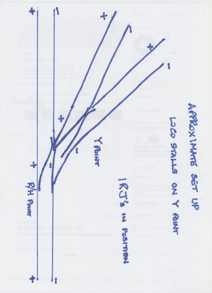
©Nigel C. Phillips
Posted

Full Member
Without that information, we're still working in the dark ……….:roll:
'Petermac
Posted
Full Member
Cheers, Pete.
it was already on fire when I got here, honest!
Posted
Full Member
all the best Kevin
Staying on the thread Kevin.
Posted
Full Member
I had left the track loose until I had tested the circuitry, and the bouncy track was halting the loco , "in its tracks ". Alas I don't have a pile of Railway Magazines and I don't buy magazines that often
thank you for help, all the best Kevin
Staying on the thread Kevin.
Posted
Legacy Member
:thumbs:thumbs;-):cool:
Owen
web-cam 2.2.74.174:8081
if the lights are off no cam
if the lights are off no cam
Posted
Full Member
It was suggested that if one glued down the track before testing the wiring one might have more trouble lifting the track, so that is what I did.
all the best Kevin
Staying on the thread Kevin.
Posted
Site staff
Ron
NCE DCC ; 00 scale UK outline.
NCE DCC ; 00 scale UK outline.
1 guest and 0 members have just viewed this.