new layout help with wiring
Posted
#245387
(In Topic #13551)

Full Member
 Last edit: by Bobby098

Posted
Full Member
I'm also running DC, N Gauge, two trains and two controllers (at least I will when its finally complete) and would say for sure you can do the same on your planned layout, isolating the track in places will be essential though. If I'm not mistaken you could even have Common Control, whereby you can switch one controller to have control over a train throughout the whole layout … or switch back so two controllers can control separate trains over different isolated parts of the layout - you have some flexibility there but depends on what you operating needs are.
I'm sure Trevor or Sol will jump in quick to give you a rough electric design plan for you …. but if not I'll have a stab at it based on what I learnt from them. Confidence is slowing growing :-)
Great to have you back
Paul
Posted

Full Member
This looks very interesting and a candidate for Cab Control - a sectionalised layout with 2 controllers and each section switchable to either controller. Happy to pitch in with some ideas - can you confirm that the right hand exit is to a storage/fiddle yard?
Welcome to the "DC Club" - we need some more members!!!

Barry
Shed dweller, Softie Southerner and Meglomaniac
Posted
Full Member
Posted

Site staff
http://yourmodelrailway.net/view_topic.php?id=12852&forum_id=21&page=1#p227065
Ron
NCE DCC ; 00 scale UK outline.
NCE DCC ; 00 scale UK outline.
Posted
Full Member
Questions?
Are you using Insulfrog or Electrofrog points… yes it will make a difference!
Are you using a Gaugemaster throttle which can use common rail or a H&M Duette style ?
As Paul outlines, yes we (Sol and myself) are happy to help and I am really pleased that Paul thinks he would be able to handle it himself with diagrams… (well done mate by the way!). I have only just come on this thread so maybe I have missed something but glad to see you on deck after a list of ills… a few of us in that situation here!
When I get the feedback, the diagram will be forthcoming!
Cheers from Australia
Trevor
Posted
Full Member
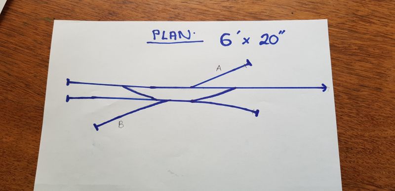
this plan is a old layout my grandson saw in a magazine when in hospital it was 00 gauge and call Evenstow he love it so I said I will build it but in N gauge so he I am now asking for your help in wiring it …..
the points are; all Insulfrog I have a gaugemaster D track controller .. maybe 2 trains running is to much ? or should I just have one train were he can maybe leave in a sidings and run another , like isolating some track like area A and B . the plan downbelow is the one he loves cant let he down .. I know people don't like copying but its never going to be exactly the same …… cheers bob
Last edit: by Bobby098
Posted
Full Member
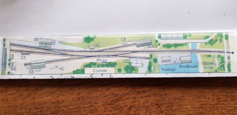
Sight unseen I made a diagram which is SCHEMATICALLY identical to the plan but more generously proportioned.
It is using common rail which is possible with a Gaugemaster and using Single Pole Double Throw (Centre Off) switches. The Insulated rail joiners are on a consistent side of the track which I have put on the "South" side of the rails. I may have overkilled with the number of blocks but you will be able to operate two trains very independently from other…
See what you think!
Regards
Trevor
Posted
Full Member
Posted
Full Member
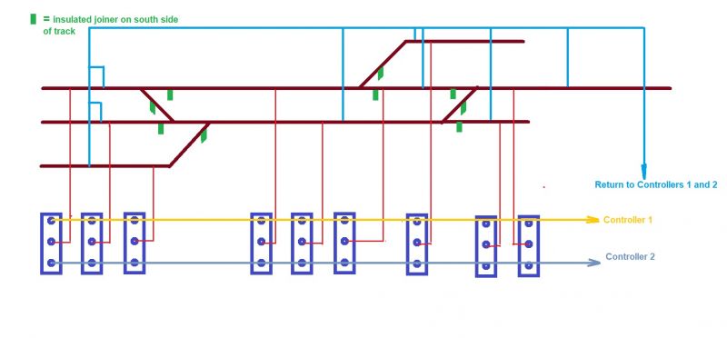
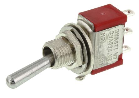
The diagram shows the underside where you would attach the wires on the switch and in fact is PHYSICALLY represented by one of these - or any other shape switch!
The controller wires can be either positive or negative depending on the direction of the controller. A schematic is simpler diagram in that you don't scale the lengths of wire but everything is relative to each other. I have not worried about point motors … an overlay of them would confuse the issue for a number of us here!
Hope this helps!
Trevor
Last edit: by xdford
Posted
Full Member
Posted

Full Member
This looks like a slightly modified Time Saver, the DC wiring of which was relatively simple. No blocks to worry about. But, (and it's a big but), only one engine.
Now DCC would be a lot easier, no toggle switches, black to one rail, red to the other, repeat as required going from one end to the other, no blocks necessary (power sectors in DCC). Running trains on a big DC system is relatively easy, once you get small with lots of points (6 in your case over 6 feet) the blocks (independently controlled sections that you switch from dead to live as the engine moves through them) become small and many. It's all a question of time spent on changing blocks and points for 2 engines. How many operators? I would say 3, one for each engine and a switch/block operator to keep track of who is where and when. Plus one for the fiddle yard.
With DCC you could run 4 engines/trains at once with no blocks and just 2 wires to the track.
Just saying….
Nigel
©Nigel C. Phillips
Posted
Full Member
Bob,one more question , do I need to get more switches for the points ? cheers bob
No! Look up your previous layout thread and you will see that we can make it with probe and contact for the points!
You will have to work out your control panel size!
Regards
Trevor
Posted
Full Member
Posted

Legacy Member
You will end up down the pig farm Nigel trying to hijack Barrys DC convertHi Bob,
This looks like a slightly modified Time Saver, the DC wiring of which was relatively simple. No blocks to worry about. But, (and it's a big but), only one engine.
Now DCC would be a lot easier, no toggle switches, black to one rail, red to the other, repeat as required going from one end to the other, no blocks necessary (power sectors in DCC). Running trains on a big DC system is relatively easy, once you get small with lots of points (6 in your case over 6 feet) the blocks (independently controlled sections that you switch from dead to live as the engine moves through them) become small and many. It's all a question of time spent on changing blocks and points for 2 engines. How many operators? I would say 3, one for each engine and a switch/block operator to keep track of who is where and when. Plus one for the fiddle yard.
With DCC you could run 4 engines/trains at once with no blocks and just 2 wires to the track.
Just saying….
Nigel
Brian
OO gauge DCC ECOS Itrain 4 computer control system
Posted
Full Member
Posted
Full Member
Sensible choice. I was just pointing out the alternative - one on/off switch. I am full of admiration for those who use DC. No judgement.
Nigel
©Nigel C. Phillips
Posted
Full Member
Bob
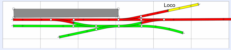
I came up with this before seeing your trackplan post - its a beauty and should make a super model.
The layout is divided into 2 basic sections - the red and green.
Each section is fed (feed and return) through a DPDT switch - thats a Double Pole (two contacts) Double Throw (two options other than "off"). They look like the ones Trevor posted a photo of and they have 6 contacts on the back. More of this later.
Each section (red or green) is fed into the centre pair of contacts on the switch. One controller is connected to the top pair and the other controller to the bottom pair.
Now you have "Cab Control" - put the switch in the centre position and the track section is dead. Push the switch UP and controller A has control of that section. Push it down and controller B has control of that section.
Thus you can have controller A dealing with an arrival or departure (on the red section) whilst B shunts (on the green section).
Note that one controller will need to have both red and green sections to run round the train. This is not such a bad thing as it is highly unlikely that on a station of this size, two engines would be allowed to move together if one is running round and occupying the platform and loop roads.
This is not affected by live or dead frogs, hand or electrically operated points, or whatever standards of track you employ.
The yellow section is isolated from the red section byb a single insulated fishplate on the FEED side. Take a wire from the red feed through a STSP (Single Pole Single Throw) switch - also known as an on-off switch! - and connect the other side of the switch to the yellow section. When the switch is up, the yellow section gets no power so an engine can be isolated. Put the switch down and the loco can move. This arrangement can be simplified by isolating the engine by setting the point against it BUT with an isolated section, you can hold 2 engines on the shed road - one isolated by the switch and the other by the point.
You can get even more clever by doing the same isolating trick with the platform headshunt - this isolates the loco that just arrived and allows a second engine into the red section to withdraw the stock, either as a departure or to shunt. This can be useful if the platform is not overlong and you don't have enough room to run round the train in the loop.
DPDT and SPST switches are available on eBay or similar. The "sub-miniature" types will handle the power and voltage ratings we experience so there is no need to buy large.
Hope this helps - ask if I have confused you. (My proposed 24x16ft layout will be wired exactly the same way as this demonstrating that cab control can be used for large and small layouts with equal success.)
Looking forward to seeing things develop
Barry
Shed dweller, Softie Southerner and Meglomaniac
Posted
Full Member
One last thought as I read through my post - make the storage area a separate section - this allows an operator to assemble trains without the possibility of someone turning a controller and his trains running off!!
Barry
Shed dweller, Softie Southerner and Meglomaniac
Posted
Full Member
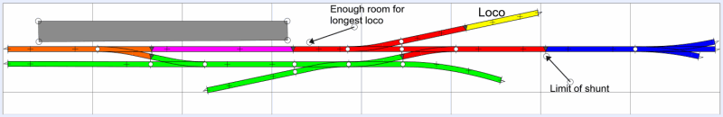
So the blue section is the storage yard. Red is the approach line that can be used by either controller to bring a train into/out of either the platform or the loop road. The break between the red and the purple should be long enough to allow a loco to come off shed without going into the purple section and this should also be clear of any stock/a train in the platform. The yellow isolating section works as before.
The purple section is the platform and allows a train to stand isolated whilst a loco runs onto/off shed.
The orange section is the headshunt isolator as described earlier and the green section is the yard.
Each section has a DPDT switch allowing it to be allocated to either controller A or B. With this version, A can take a loco from the headshunt into the loop where the water crane awaits (using orange and green sections). Meanwhile, B uses yellow, red and purple to bring a loco from the shed to couple up to the stock in the platform and then gains blue to depart.
If all this sounds like the sort of thing you want to do, I will happily produce a detailed wiring schematic for you.
If this makes you go "two wires to the track" DCC, I don't blame you!!!! Only joking :lol: :lol:
Barry
Shed dweller, Softie Southerner and Meglomaniac
1 guest and 0 members have just viewed this.