Double Slip wiring
Posted
#90919
(In Topic #4877)

Full Member
Simple pimple..........
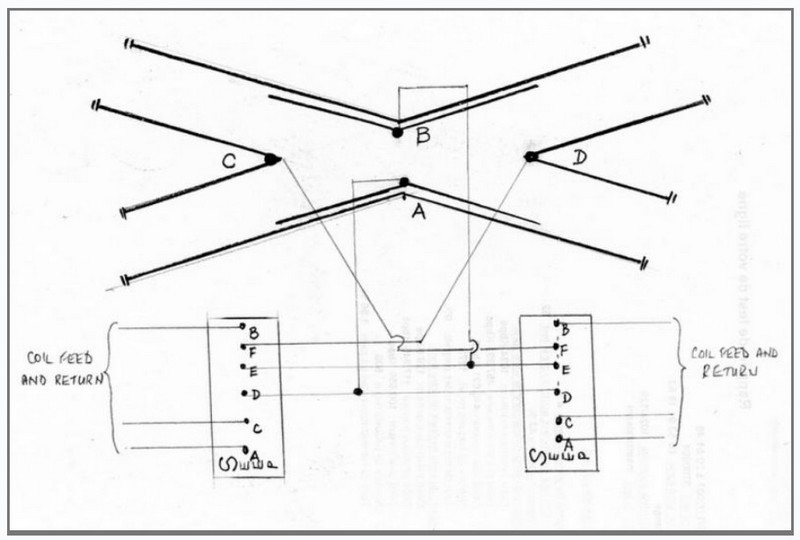
[Shown for SEEP motors]
The thing to remember is that the point motor switches at one end of the slip control the polarity of the frog at the other end……………once you get your head around that, it all makes more sense. Positive and negative feed are also applied at 'A' and 'B'.
Doug
'You may share the labours of the great, but you will not share the spoil…' Aesop's Fables
"Beer is proof that God loves us and wants us to be happy" - Benjamin Franklin
In the land of the slap-dash and implausible, mediocrity is king
"Beer is proof that God loves us and wants us to be happy" - Benjamin Franklin
In the land of the slap-dash and implausible, mediocrity is king

Posted
Guest user
Could a member or members help please?
All my 00 gauge points are code 100 live frog: except that is my double slip which has insulated frogs.
It has no point motors only my index finger;-).
Please could someone put a simple diagram of where the feeds and any insulated rail joiners will go.
It is connected directly to a live frog point.
Thanks in anticipation,
Jeff Rippon
Posted
Full Member
Doug
'You may share the labours of the great, but you will not share the spoil…' Aesop's Fables
"Beer is proof that God loves us and wants us to be happy" - Benjamin Franklin
In the land of the slap-dash and implausible, mediocrity is king
"Beer is proof that God loves us and wants us to be happy" - Benjamin Franklin
In the land of the slap-dash and implausible, mediocrity is king
Posted

Inactive Member
Here's how to hook up the rails.
If it is an insulfrog turnout, put insulated joiners on every (8) track join. Then put dropper wires on each of the rails at each end of the turnout. Start with the rail furthest from the edge of the layout, then go red, black, red, black towards the nearest. When you do the other end of the turnout, you can dispense with the two outside rail droppers if you like, because they would have been connected at the other end.
Is that helpful?
Max
Port Elderley
Port Elderley
Posted
Guest user
If it is DC, you can trat it as another section/controller selection switch.
If in doubt, have a good read of this http://brian-lambert.co.uk/Electrical.htm#Points
Posted
Guest user
Using insulfrog points makes wiring simpler as the points can be used to isolate track sections but you then have the inherent drawbacks of those points in terms of train performance and track appearance. You can still get a short if you forget to set the points against the crossing route but good signalling and regulation will ensure this doesn't happpen!
Posted
Guest user
Sorry but I'm still having trouble understanding your instructions.
Firstly I am using DC not DCC.
As already stated my points are live frog, only the double slip has insulated frogs.
Aren't the plastic frogs of the double slip in lieu of putting in insulated rail joiners?
If I add insulated rail joiners to the frogs presumably that will give me belt and braces?
I then solder wires to each of the outside curved rails and these can be connected with nickel silver rail joiners to the other track?
Does that sound correct please?
Regards,
Jeff
Posted

Full Member
Putting insulated rail joiners on all the ends of the tracks on the slip, is different. That insulates the whole of the slip from the rest of the layout. Then you have to connect the power using Max's explaination to each bit of rail using droppers. The frogs (being already insulated) will take care of themsleves.
As far as I know, they (Peco) only make insulfrog double slips. I suspect the wiring for electrofrog ones would be a nightmare for amateurs.
'Petermac
Posted
Inactive Member
Jeff is DC, so in the interest of simplicity, I suggested isolating the turnout from the rest of the trackage. Then you can connect the turnout sub-bus to which ever block suits your operating needs.
Max
Port Elderley
Port Elderley
Posted
Guest user
In the case of a double slip there are more rails and more continuous routes for power to feed through. That was one aspect which caused me some problems wiring mine. The plastic frogs fulfil the same function as they do anywhere else but instead of three track ends you have four and instead of two routes for trains to take you have four again. Therefore it is good advice to completely isolate the unit and switch the current as you require.
My track plan means I don''t need to do that much as I can isolate routes by setting other points against them but that will not be true for all layouts. I only have one pair of rails insulated which is where the cross-track goes from down to up and that is only to prevent shorts. Trains can be driven across the gap without stopping by using the controllers for both circuits.
Posted

Full Member
They're not too bad, Peter. I have two double slip electrofrog turnouts on my RR&Co layout and with the Tortoise motors, it was simple to switch the frog polarity.
Are they handbuilt Max?
Posted
Inactive Member
Max
Port Elderley
Port Elderley
Posted
Full Member
Just shows - keep your mouth shut Petermac unless you're sure of your facts !!!!! :oops::oops::oops:
'Petermac
Posted
Full Member
However, I do understand what is required for DC and wondered if a simple diagram might help Jeff here. I think that an insulated double slip connected to an electrofrog point would look like this:-

If I am correct, then all of the red rails on the slip are joined together by Peco, as are all the green. (Incidentally this is very similar to the electrofrog code 75 version except in the area of the frogs.) If I am wrong about the internal connections, I apologise now and will change the picture as soon as someone tells me different!
Continuing to assume that I am correct, this means that very little needs to be done to wire up the slip, and I think that is the aim with insulfrog. Not sure where you have your electrofrog point connected, Jeff, but where I have shown it would only mean using two insulated joiners at its frog as usual.
You say you are not using motors, just fingers, so I think nothing else is needed. The blue rails on the electrofrog are all joined together and change polarity according to which switch blade is against its stock rail. As shown, the blue rails would be powered by the green stock rail.
Hope this helps.
 Last edit: by Geoff R
Posted
Guest user
Thanks for your post. Certainly you have shown the arrangement of double slip and point that I have.
However, looking at the coloured rails I can't understand how the routeings have been set.
If coming into the d/s from the lower left hand track I have 2 routes to go; either ahead across the crossing or towards the horizontal right hand track. It just seems the switch rails shown doesn't show this but perhaps that is draughtsmans licence?
If just adding 2 insulated rail joiners where shown is right, and I don't mean to doubt you, this arrangement is far simpler than I had assumed.
Could you just check your arrangement please before I fit new rail joiners.
Thanks,
Jeff
Posted
Full Member
If the right hand blades were pushed upwards, then in the first case above the route would be from the lower left track to the lower right track, and in the second case from the lower left track to the upper right track, i.e. the other point.
I believe that the key aspect of the insulfrog slip is that the rails are always powered as I have shown them. Now switching occurs when the blades are moved. This is EXACTLY the same with the electrofrog code 75, except that the frogs have to be switched due to the two rails that make them up being electrically connected to each other.
Are you not able to connect it up as shown and attach power to check that it works before making anything permanent? You could use a 9v battery as a quick test.
Posted
Guest user
Thanks for your posting.
With a bit of fiddling and some additional switching the double slip now seems to work on all routes.
I also apologise for doubting your drawing. I had not figured out it is possible to set a route other than the correct ones.
To all those who also posted replies - many thanks.
Regards,
Jeff
Posted
Guest user
1 guest and 0 members have just viewed this.