Cobalt point motors
Posted
#160676
(In Topic #9104)
Guest user
Wiring accessory switches for route indication
Here's one for the Cobalt users amongst us.Having decided ( Ithink ) to go with Cobalt point motors ( DC mimic panel operated ) I just need to clear the wiring theory in my own mind .
When looking at the Cobalt instruction manual on the Gaugemaster website, I have came to the following understanding, can someone confirm my theoryonthis or otherwise set me straight.
There are eight terminals. The extreme outer terminals are for the positive and negative for the point switch operation.
Next, there are two commons, one for SPST switch one and the other for SPST switch two. In other words……two accessory switch common feeds.
This leaves four terminals,two per accessory switch.
If we take accessory switch one for example, when the point switch is thrown one way this will automatically throw the accessory switch one ( say for route indication ) and the led wired to that route will light up. When the point switch is thrown again the accessory switch will switchover to the other contact and light the LED indicating the other route has been activated.
To clarify my understanding, the Cobalt switches the LEDs automatically when you fire the point switch. The two terminals T1 and T2 are switched between automatically and connected to the common depending on what route you set the point to. Phew……………:mrgreen::pedal…….I'm glad I got that off my chest……..now what do you think ?
I take it that the second accessory switch changes the track polarity on the same principle.
I know……..me a spark too…..:oops: ….a however, even us electrical geniuses need a bit of reassuring ever now and again as this is quite different from your everyday house wiring etc.
I'm just checking you understand…….

Now,bring on the experts
Cheers
Toto
Posted
Full Member
As another option - if you are using a mimic board, won't the position of the DPDT switch you are using not be enough to show which way the points are set?
 Last edit: by RFS
Robert

Posted

Site staff
That is why I use LEDs as well
Ron
NCE DCC ; 00 scale UK outline.
NCE DCC ; 00 scale UK outline.
Posted
Guest user
I'm sorry to labour the point as I can usually get my head round most concepts but sometimes they just take a bit of time to sink in. It may be an age thing :hmm
However, at great risk of sounding totally thick, I'll continue with my understanding of the differences between my theory and your suggestion as per the Cobalt instructions as read.
If I were to wire it your / Cobalts way as illustrated on page 12, this would involve using Cobalts switch which has a PCB incorporated into it and which operates a Bi - polar LED which shines red or green depending on which way the point is thrown. This means one LED inserted onto the mimic panel which in my mind tells me nothing.
If it is possible to use my method, apart from a bit more wiring which is not an issue for me, I could have an LED wired to each of the "switched" terminals which when the switch is thrown would operate either one LED or the other. The two LED's would be located, one on either track leg on the mimic panel which would light up the leg which theogony blades favour for route selection giving a visual indication of which track is in operation.
My main point ( excuse the pun ) being that one bi - polar LED cannot distinguish which track is the chosen route, or have I misunderstood the principle behind the operation ?
Sorry if I'm being a bit thick here. As I said previously, sometimes it can take me a bit of pondering before the eureka moment hits.
Ron I'm with you, I like LED's as they tell you at a glance. Switches alone do not. Especially with my eyesight.
Cheers for now
Toto
Posted
Site staff
so the same can be used for Cobalt.
While the Cobalt manual shows a bi-colour LED, it does say separate Red & Green LEDs can be used - of course you could use a bi-colour LED in each track on the panel - red = no go & green set. Again you are not obliged to use DCC concepts toggles with PCB - they can be wired direct from one of the changeover switches on the Cobalt.
Ron
NCE DCC ; 00 scale UK outline.
NCE DCC ; 00 scale UK outline.
Posted
Guest user
One of the reasons I was looking at the Cobalt switches is that they have the required capacitors for LED operation " built in ". This saves more soldering which Iam trying to keep to a minimum.
If I wire the LED's straight from the cobalt motor switching, would I not have to wire capacitors in series between the motor and the LED's.
One more point, if I was to add a second LED in series to a given route to extend the route indication along the chosen track selection on the mimic panel, would I need to add or change the value of the original capacitors?
Hope I'm being clear here. I am at a stage with my layout build where I am constructing an over head gantry to house my mimic panel. Once I have this done and the baseboard finished, I shall be laying track. With this in mind, as the track goes down andI am satisfied that I am happy with it, I will be ordering the switches ( if I use them ) and marking out the mimic panel for wiring etc.
Thanks for your continuing patience.
Cheers
Toto.
Posted
Site staff
Ron
NCE DCC ; 00 scale UK outline.
NCE DCC ; 00 scale UK outline.
Posted
Guest user
I have read various guides etc including versions kindly recommended by yourself but sometimes, until I get. True grip of something, I need a bit of confirmation . Hope I'm not being a PITA.
Much appreciated, I will no doubt be confirming my understanding of whatever advice I may get back to the forum ( belt and braces ) just to get it into my own words and through my rather dense grey matter.
Thanks again
Toto.:oops:
Posted
Site staff
If it is possible to use my method, apart from a bit more wiring which is not an issue for me, I could have an LED wired to each of the "switched" terminals which when the switch is thrown would operate either one LED or the other. The two LED's would be located, one on either track leg on the mimic panel which would light up the leg which theogony blades favour for route selection giving a visual indication of which track is in operation.
yes, viable.
the actual Cobalt does not have in built resistors for LEDs, they are external mounted by the User being part of the LED circuity & using one of the change over switches internal to the Cobalt - as depicted in the Tortoise sheet.
The resistors you are talking about are those already wired to the PCB & toggle - associated with the Cobalt if you use that method.
Ron
NCE DCC ; 00 scale UK outline.
NCE DCC ; 00 scale UK outline.
Posted
Guest user
I think Im getting there……..slowly.
Cheers
Toto
Posted
Guest user
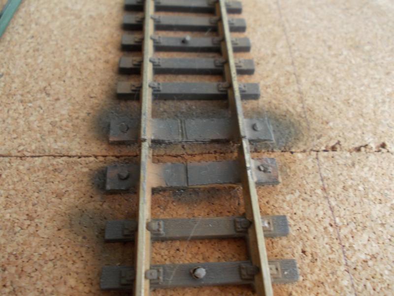
I have seen the mods for the Peco turnouts where copper clad sleepers replace the gaps left when taking out the spring housing etc.
Now, probably about to show my misunderstanding of te whole modification but if you use copper clad sleepers, does that not create a short between the two tracks ?
Tell me if I'm going mad or just plain stupid.
I will be about to undertake this modification to about 3 dozen sets of turnouts so understanding the mod would be advisable I think.
Sol, if I've not tipped you over the edge already
 : this could be one for you.
Many thanks:oops::oops:
Toto
Posted
Full Member
I've done the mod on all my Peco turnouts operated by Tortoise motors, but I just replaced the sleepers removed with spares from track off-cuts, making sure the chairs were filed off so that they didn't impede the movement of the blades.
Last edit: by RFS
Robert
Posted

Banned
Cheers, Gary.
Posted
Guest user
Thanks for that. I had thought of using spare sleepers from track off cuts but then thought……….mmmmm is that cheating ? But, if its good enough, then that'll do for me. Sounds a whole lot easier.
Cheers for now
Toto.
Posted
Site staff
Tom, Page 18 of the Cobalt manual which talks about replacing the plastic sleepers with PCB/copper clad sleepers, makes reference to providing the isolating gap.Another query regarding Cobalt and turnouts.
I have seen the mods for the Peco turnouts where copper clad sleepers replace the gaps left when taking out the spring housing etc.
Now, probably about to show my misunderstanding of te whole modification but if you use copper clad sleepers, does that not create a short between the two tracks ?
Tell me if I'm going mad or just plain stupid.
I will be about to undertake this modification to about 3 dozen sets of turnouts so understanding the mod would be advisable I think.
Sol, if I've not tipped you over the edge already
Many thanks:oops::oops:
Toto
Ron
NCE DCC ; 00 scale UK outline.
NCE DCC ; 00 scale UK outline.
Posted
Guest user
Is this passing ships or what…….I must have just missed your post.
I think I'll stick with the plastic unless there would be any benefit in using copper clad or PCB in a specific location.
I have so many new skills, idea's etc that I will need to be using going forward at the early stages of the build that I need to try and keep it as easy as I can otherwise it could bring me to a halt. If something is necessary or a true advantage either operationally or cosmetically then yep I'm all for it.
I think the main modification itself makes the biggest contribution in improving the look of the turnout. I doubt most would notice if the replacement sleepers were plastic or copper without really scrutinising them. And………..I won't be providing any close ups
Thanks again.
Toto
Posted
Guest user
My apologies,
I've either not read it properly or misunderstood what they meant.
However, I now get the picture. Thanks again.
Toto
Posted
Guest user
Get the ropes out, further queries on these Cobalts.
I am powering my track via my controller bus wires. Great….easy. I am powering my Cobalts from a separate DC supply ( Cobalts own PSU 2+ ).
From which I am running another bus purely for the Cobalt supplies.
So the track including points from the controller main bus and the cobalt motors from the Cobalt supply ( points bus ).
When it comes to the frog polarity. The frog will be dead as I have taken out the links on the underside of the track ( 2 no ). I am assuming that the feed to the frog comes via the switch from the cobalt.
In order to get a supply to that accessory switch, do I just place a link into the main cobalt supply or do I get that from the track supply which would mean that I am mixing the supplies from both bus systems.
My own head tells me it is the first option as I would not like to have two separate supplies from different sources going through the Cobalt.
What it would mean is that the main rails on the points come from the power bus whilst the frog is fed from the Cobalts. ( I think ).
Again, apologies if this is a no brainer.
Cheers
Toto
Posted
Full Member
Robert
Posted
Guest user
this essentially means that there will be two supplies to the Cobalt.
supply one terminals 1 and 8 powered from my point motor / accessory bus and terminals 2 and 3 to the track bus and terminal 4 ( common ) back to the frog. If I understand correctly.
ok thanks for posting
cheers for now.
Toto
1 guest and 0 members have just viewed this.