Bachmann J72 Decoder Install
Posted
#202517
(In Topic #11180)

Site staff
Maybe
Although I said I wouldn't try an put a decoder in this loco a long time ago it being split chassis, I did attempt it last year with not very good results.I though I might get away with a Hattons own make but it blew for no apparent reason, so I installed a Digitrax DN136D which has a higher maximum current rating (1.5 Amp). Unfortunately this also blew after a bit of testing and as I know there were no short circuits I can only assume the motor can occasionally draw a much higher current for very brief periods .
Pictures from last August.

Space is a problem, but some months ago I bought a Lenz Standard Plus which although a bit larger than the Digitrax, I'm led to believe will physically fit.
The Lenz (allegedly) has a 1A continuous, 1.8A max, > 5 A stall current capacity and with this in mind I finally got around to testing.
Got some very odd readings when trying to stall the loco, including one briefly of 2.6Amps, but in general it was only using about 0.6.
Of course, if I'd done this first I wouldn't have blown the other two decoders :oops::oops::oops::oops:
I am going to try and install the Lenz this week-end, so watch this space as they say.
Ed

Posted
Full Member
At least the Lenz decoder has an overload cutout, although I wouldn't rely on this for too long a time.
In all of the split chassis conversions I have done, I have wrapped the motor casing with insulating tape to isolate it from the chassis. In all my cases, though, the motors were of the totally enclosed type (that's for two Lord Nelsons, a pannier tank and an Ivatt 2-6-2T, plus an 04 diesel shunter).
 Last edit: by SRman
Jeff Lynn,
Amateur layabout, Professional Lurker, Thread hijacker extraordinaire
Amateur layabout, Professional Lurker, Thread hijacker extraordinaire
Posted
Site staff
I might put some insulation tape around it as well, if there's space.
Thanks for that.
Ed
Posted

Full Member
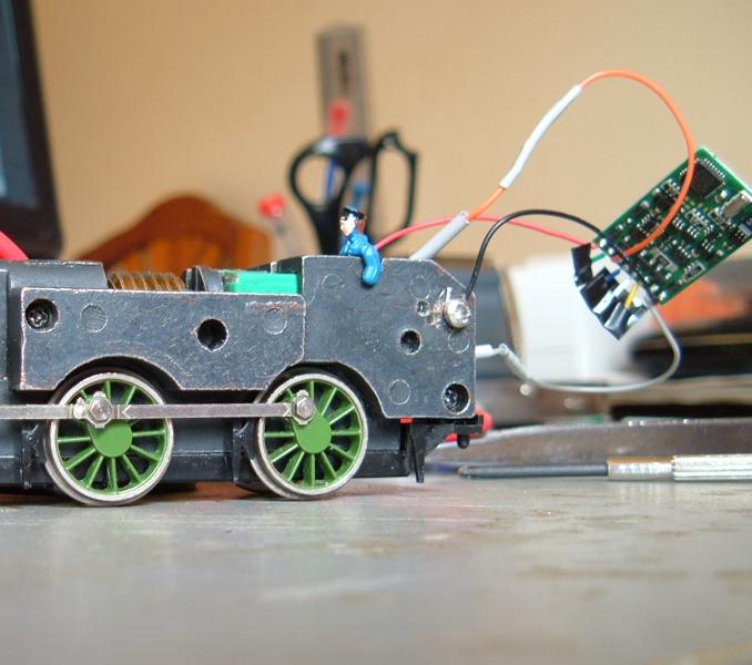
Not clear from the photo but are you drilling and tapping the frames for power or is that blue tack holding the leads in place?
Again, not clear from the photo, but that looks like heat shrink going over the motor terminals. The paint Bachmann uses is conductive, and is over a thin coat of copper plating on the MAZAC (about 50 µm). You might be having momentary shorts if the terminals are not completely covered and they touch the frame sides when torque is applied. The original setup had spring contacts which were intended to stop this. I've had this problem in the past with split frames, taking some #200 emery and rubbing back the surfaces that the terminals were supposed to touch followed by a very thin coat of 5' epoxy solved the problem. The other approach is to use liquid insulation, used by electricians, and cover the terminals and frame surfaces with that.
That plastic sleeve is not efficient, coat the frames with epoxy or use some insulating tape or foam tape over the metal. The latter allows some compression when assembled and stops the motor rotating from torque. Not a good idea to wrap the motor, no ventilation of the innards. You might also want to check that the plastic spacers keeping the frames apart are all as they should be. Some styrene shims will do the job. Check the resistance between the two halves when its all bolted together. If the nuts/bolts are iffy spares are available.
I've run these motors (and larger) quite happily with n-scale Digitrax decoders rated at 1 amp or thereabouts. Sounds to me as if you are getting momentary shorts at the higher DCC current. I wouldn't use an expensive decoder until I was sure there were no shorts. Consider using a 6 or 8 pin plug (or even 9-pin JST plug) wired to the frames/motor, and plug the decoder into that rather than hot-wire it every time. That way you can check with a cheapy, run with a decent.
Nigel
©Nigel C. Phillips
Posted
Site staff
This was one option I tried before using self tapping screws to connect the wires to the chassis/frames, which can be seen in some of the following pictures.
(Blu-Tack is not a very good conductor :roll:)
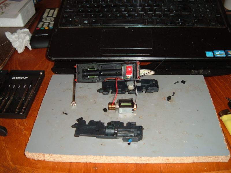
The plastic sleeve (for want of a better term) in the following picture comes in two pieces.
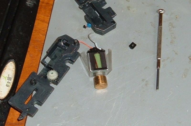
The bit on the left is sort of 'L' shaped and covers the front of the motor as well as the side, going over/around the boss which holds the armature spindle.
The bit on the right slides under the 'L' shaped bit when it's all put together (as shown here),to provide insulation between the motor and chassis/frames.
Although this had all been tested with a continuity meter, I thought I'd take Jeff's advice on-board and add some additional tape.
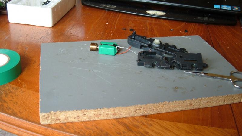
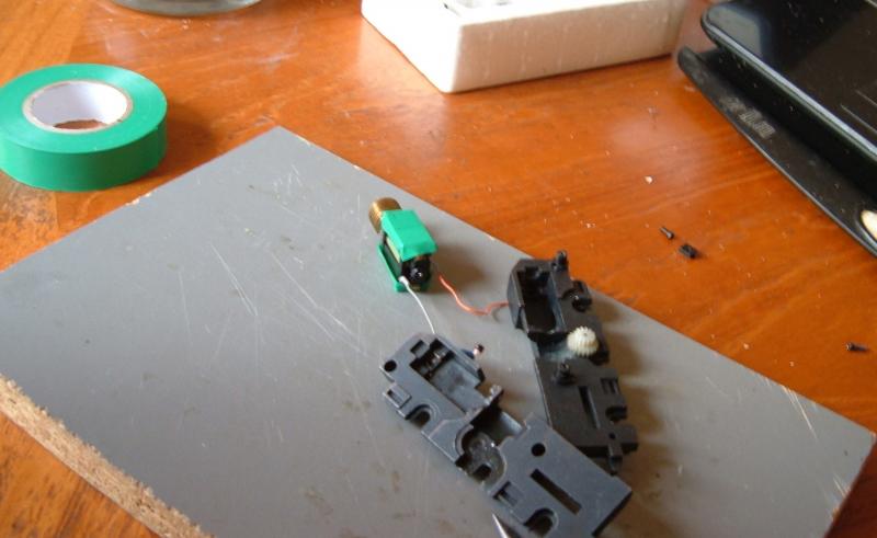
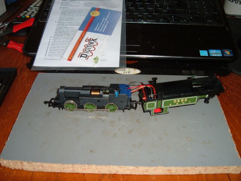
The connections are how I left it last year, with the wires from the motor terminals attached to the chassis/frames thereby making the loco DC.
To install a decoder all I have to do is disconnect the current orange and grey wires from the screws and solder them to the orange and grey on a decoder. The red and black from the decoder then get attached to the screws on the chassis/frame. Simples

Since adding the tape I have checked (yet again) with the continuity meter and there are (still and not surprisingly) no shorts.
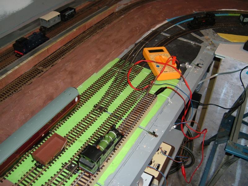
Further testing with a number of multimeters (don't really trust these cheap ones to be that accurate) appears to confirm that the stall current is low, and would not blow a decoder.
However, when testing the surge current produced from going from stop to full power I get all sorts of large reading across all the multimeters.
Think this may be where my original problem may lie.
Not that I would go to full power from stationary anyway, but if I changed the appropriate CV's in the decoder to limit start voltage etc.
would that stop an excessively large current from being produced ?

Ed
Posted
Full Member
Chassis tapped, no short circuits, voltage spikes when going from stop to full power on DC. I would assume the problem is with the motor (or the wiring). Does this motor have one of those disc capacitors in the motor (for RF)? I know more recent Hornby motors have this. If it's not working could explain the spikes. Are any of the commutator plates loose? Did you check the brushes? Might be worthwhile replacing them. How clean is the commutator? This is a 3-pole motor, would cogging induce a spike? If the motor is generating spikes then controlling the maximum voltage to the motor through the CV's may not stop it frying the decoder if it does spike. Would BEMF protect the decoder? Those more experienced than me in this field step up please.
Nigel
©Nigel C. Phillips
Posted
Site staff
It's not really that old, I bought it around 1995 when it was new and it's been little used.
(Price label is still on it. Cost me £26.50 at the time
 )
)If the multimeter readings are near enough correct, I cant see why when going from stationary to full power wouldn't trip a DC controller, most of them being rated at 1 Amp.
Brian Lambert, once of this parish, did one here.
Scroll down a bit from the Ringfield, past the J94.
http://www.brian-lambert.co.uk/DCC.html#The
Ed
Posted
Full Member
I was clutching at straws there. If the chassis is OK then it's the motor or the wiring to the track. If there was no circuit board with capacitors they may be inside the motor (although where is a question). Capacitors withdraw electrical spikes (from the brushes/commutator amongst other things). If it's not the wiring (try twisting the wires together to see if the spike is still there) then I would not risk an expensive decoder with this motor.
Were the decoders fried or did they just lose their programing?
Nigel
©Nigel C. Phillips
Posted
Site staff
It's a Bachmann can motor, no caps or anything else.
It was nearly a year ago, but from what I remember the Hattons decoder was just totally dead and the Digitrax gave intermittent results, sometimes showing the loco address as 2 instead of 3.
At the time I removed it from the J72 and installed it in Hornby Pug, but I got the same results and whatever loco address I used it won't run the motor.
A cheap decoder is more likely to blow, as they have a lower maximum current.
Ed
Posted
Full Member
If you are seeing ampere spikes, it's either a constant resistance with a voltage spike, or constant voltage with a decrease in resistance (if I remember this correctly - I=V/R). Unless the DC powerpack is fluctuating widely, changes in resistance would seem to be the culprit (depending on where the brushes land when stalled and how reproducible the windings are on the 3 poles), and probably from that 3-pole/3 segment commutator setup in a motor not ever intended to be run under DCC.
What's the DCC supply putting out? 5 amp? Mine is 2 amp nominal (NCE, enough for the 2-3 engines I run).
Now you could always tow a van around with an O-scale decoder ticked inside. Followed by another van with some very loudspeakers. Or just get a new motor intended to be run under DCC. I suspect a Lenz decoder rated at 5 amp (and that will be momentarily) will be a band aid.
You have checked the split axles/gear for splits? It's the right age. The Achilles heel of the Bachmann split chassis design. If you haven't checked I'd do it before spending any more money.
Nigel
©Nigel C. Phillips
Posted
Site staff
My thoughts are that using CV5 to restrict the DC voltage rectified by the decoder and then being sent to the motor, would therefore limit the maximum current that it could draw.
In normal running at reasonable speeds up and down the test track it's only pulling around 300mA.
More testing to be done.
Ed
Posted
Full Member
I have no experience of Gaugemaster equipment, is this a pulsed supply? Output from the specification sheet is 12v 1 amp, presumably rectified. If you are seeing spikes of 2-3 amps……
Digitrax decoders really don't like DC (neither do a lot of other decoders). The start voltage is about double that under DCC (Digitrax says 5-6 volts but I recon it's more like 7-8 volts) and they definitely do not like pulsed DC. Digitrax in fact suggest using a blanking plug (for the JST connection on the decoder) when running under DC. Lenz decoders can also behave erratically with DC. The Lenz operating manual states only DC systems that conform to NEM (Normen Europäischer Modellbahnen) should be used*. The standards are only available in French or German.
You may be having a problem with the DC supply and subsequently "frying the chips", the motor may be perfectly OK. I suspect if you keep the decoders away from the DC supply you should be fine without resort to limiting the voltage range. Which is why I was asking about the DCC output (not the DC output).
For these reasons a lot of people (including myself) do not run decoder-equipped engines with DC. After "frying" some DCC sound decoders I now follow the sequence: DCC wiring conversion with an 8-socket wiring harness (or 6 if it's a small engine with an N-scale decoder), test the wiring under DC with a blanking plug, then el cheapo decoder and DCC, then the decoder of choice. If it goes back to running on DC it's with a blanking plug. Bit more work, and it may mean some judicious removal of material from the chassis to get everything to fit (6-pin plugs are a lot smaller than 8), but it allows checks to be made throughout the conversion. The J82 can stand having some metal removed from the tank sides, or from the front/top of the boiler. Don't bother milling, a big coarse-cut file works fine and does the job in the time it takes to set the mill up.
Nigel
*ESU and Lenz of course conform to NEM and where appropriate NMRA (for the most part). Digitrax?
©Nigel C. Phillips
Posted
Site staff
There is no DCC chip in this loco at present and no decoder that was ever in it, was ever near a DC supply.
As I said, there is hardly room for a decoder, yet alone a socket.
For interest and I quote Gaugemaster:-
"The controller is not pulsed and regarded as standard, however it is not a smoothed regulated unit like a power supply.
Greg Spears
Technical Department"
Ed
Posted
Full Member
So when it had a decoder it was only run on DCC? Then I'm not sure of the relevance of spiking on an unregulated DC supply to a regulated DCC supply. So it's still down to the motor or you do have a short somewhere (or wiring issues). Or you were really unlucky with 2 faulty decoders.
You can get a small decoder and a socket into one of these. All depends on how much hacking you want to do. The Lenz decoder that plugs straight in would be easier…and having a socket means you can test the decoder on a locomotive (or decoder tester) with no issues prior to installing it on the new one.
What are you doing with the fx wires? No bare wires/shorts there?
Hope you get it sorted.
Nigel
©Nigel C. Phillips
Posted
Full Member
In doing some internet trawling (for something else) I came an article describing commutator spiking (4 amp) from an Athearn motor and how this could be controlled by a resistor (3-5 ohm) in series with the motor if necessary (apparently Digitrax decoders can handle this). The link is LAMRS Equipment, Installation of a Wired DCC decoder in an Athearn "Blue Box" loco
Not my field, perhaps others could comment.
Nigel
©Nigel C. Phillips
Posted
Site staff
Meanwhile, after further testing I've decided the current readings I'm getting from these cheap Mulimeters are in general rubbish, and I'm not going to invest in a Fluke that would never get used again.
The best readings from one of the meter are around 200mA - 300mA during running and about 500mA - 600mA on a stall test. Trying to get a current spike by going from stationary to full power or reversing direction I can occasionally get a reading of 1.6Amps, which may explain why the Hattons decoder died and the Digitrax gave odd results.
Since I've already got the Lenz standard + and it's maximum current rating is 1.8Amps I'm going to fit it over the week-end and see what happens.
Ed
Posted
Full Member
Goforit! I suspect a decent decoder will be fine especially as you will limit the maximum voltage. On the basis of the spec's I got a brace of Lenz Silvers for some remotoring projects that don't require sound.
Is it just this model/ motor that gives the transient spikes?
Nigel
©Nigel C. Phillips
Posted
Site staff
Despite all my efforts there was some sort of short across the split chassis and the decoder couldn't be read on the programming track.
After taking it apart for the umpteenth time and apply more slivers of insulation tape and was absolutely 100% positive that there were no shorts anywhere.
 put
putFinally managed to read the decoder and change the default address, and …………………………………………………………
it will only go backwards :thud
Soldered the plug back on and tried the decoder in my Single Wheeler, same result.
Odd thing is, I have to put the throttle round to about 75% before it gradually starts moving and when the throttle is put to stop it gradually slows down. Almost like CVs have been set up to simulate acceleration and braking, even though I have reset the decoder to it's defaults a number of times.
Don't know if it's something I did when it was on the programming track and shorting, or whether it's a dodgy decoder.
I know a lot of people on here praise Lenz decoders but both the red and black wires came off mine, although I had been very careful when handling it, and I had to solder them back on.
Not impressed.
So the loco is working again on DC and now back in it's box in a cupboard.
Ed
PS Can't win 'em all.
Posted
Legacy Member
:thumbs;-):cool:
my webcam link 6.19.184.67:8080
Posted
Site staff
Even if it was a dud, I couldn't really send it back as I bought in February and of course I cut the plug off.
Anybody reading this who has one of these and wants to convert it to DCC, please don't be put off by my efforts. As long as there are no shorts and you can find a suitable decoder it will work.
Mine is staying in the cupboard for now.
Maybe a little job for next year
Ed
1 guest and 0 members have just viewed this.