Wayne's South Shore Baseboards
Posted

Full Member
No, I have absolutely no train loco's cars or anything! that will change here quite soon I think, once I decide on which DCC system to purchase. I am trying to keep from "Jumping the gun" but it's very HARD!
Wayne

Posted

Full Member
Wayne, you have an excellent 'blank canvass' there to start what i know is going to be a fantastic layout.
Happy building and remember "All the Big Brothers are watching you"

Brilliant job so far:doublethumb:doublethumb
'Kev
Posted
Guest user
Alan, my handicap is that I'm left handed!
That explains it allWayne
Posted

Full Member
How on earth do you keep everything so clean and tidy n that space :exclam:shock::question

Posted
Guest user
With all that spare foam Wayne, you should be making these yourself. We all know how good a handy man you are now, so no excuses! go on, at least give a go, in fact think what you could achieve with all that spare foam, the only limits are your own imagination and what your locos will handle;-)then a trip to the train store to get the Woodland Scenics Inclines on Wednesday.
Posted
Guest user
Just one question has been bugging me for a few days. Perhaps I'm being thick, but why the gap between the L shape board against the wall and the U shape one nearest the camera :question Is this where you gain acess into the adjoining room, so is where your lift out section will be :question
Posted
Full Member
I guess it must be difficult to see in the pictures, but there is actually two "gaps", one right next to the L-section and another one that is, as you say, nearest the camera. They are all access lanes for me to reach the layout. If you take a look at the track diagram it shows it much better.
Tim,
You ask, How do I keep it so tidy? Well there's a very simple answer to that, one I'm quite sure you'll understand, it's ………..SHMBO………nuff said! :roll::roll::roll:
Lawrence,
I know I said I wanted to scratchbuild everything, but those Woodland Scenic Inclines are so easy to use, and work so good, well ………. their already on order! :pedal I did think about it though!
Kevr,
"All the Big Brothers are watching you"
Yeh, I know! :It's a no no :It's a no no :It's a no no
Wayne
 Last edit: by Wayne Williams
Posted
Guest user
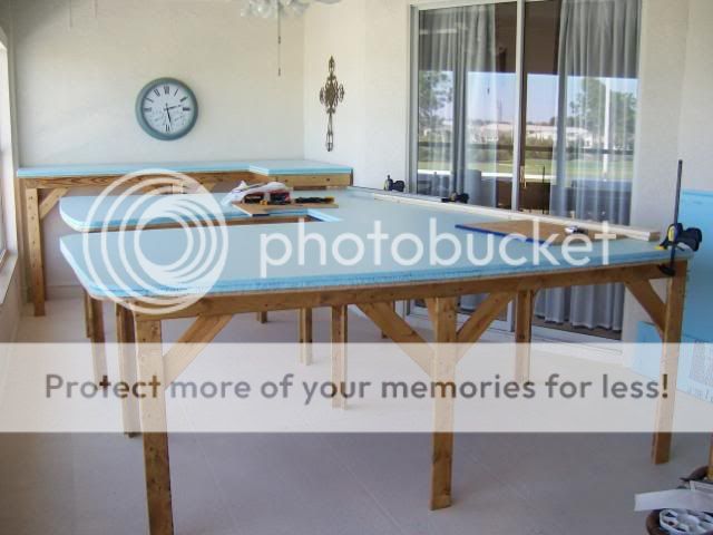
There are two seperate baseboards (or sets of boards joined together), one is an L shape (underneath the clock) and the other is made in a U shape (and is the one nearest the camera). Now there is a gap between the two board sets, where you can see the wall next to the large window. This is the gap I'm talking about. Question .. why are the two sets not joined and how is the gap to be bridged.
Posted
Full Member
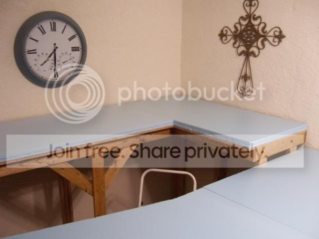
The L-shaped table is 7" higher than the rest of the layout. The train must climb that height to get up there.
Did that help?
Wayne
Posted
Guest user
What a plonker I am :exclam:exclam I could see the end grain of the bracing and "saw" a gap between the two tables instead of a height difference  :roll::roll:
Now looking at the earlier photos it's obvious. Thanks Wayne, that one has had me scratching my head for days
 thud
thud
Posted
Full Member
Wayne
Posted
Guest user
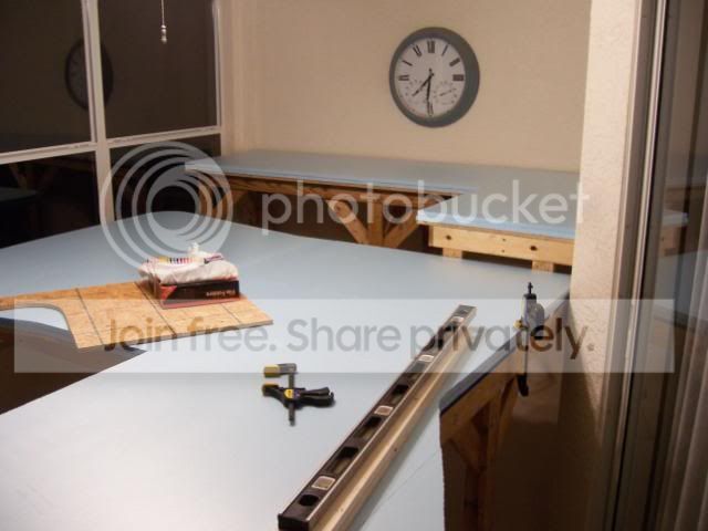
Now that gradient would be a perfect excuse for a fantastic multi-arched viaduct :exclam
Posted
Full Member
Now that gradient would be a perfect excuse for a fantastic multi-arched viaduct
:hmm :hmm :hmm
Wayne :doublethumb
Posted
Full Member
, now you have shown a pic to better explain it makes sense now.What a lovely blank canvass you have.
Phill
Posted
Full Member
Tim,
You ask, How do I keep it so tidy? Well there's a very simple answer to that, one I'm quite sure you'll understand, it's ………..SHMBO………nuff said!
I would even dare think such a thing, Wayne. :shock::shock::shock::shock: I know my place in life :???:
Posted
Guest user
I was a little confused with the layout of the baseboards, I thought that you were having a gap between them, this being were a multi-arched viaduct would have gone. But it all falls into place now, sorry.
With the game of golf out of the the way, we can look forward to seeing the inclines put into place. :Happy
Posted
Full Member
If all goes well, this afternoon, I will go over to the train store, and hopefully the inclines will have arrived. So you can bet your booty, I'll be back home and rarin' to go.
While I do have a layout drawing to follow, there will be some serious thinking going on as to the heights involved for those inclines. So if you smell something burning over there, don't worry, it's just my brain!
Wayne
Posted
Full Member
I am disappointed in all of you for not warning me about how difficult it is to layout the track.
It is fun though! I think I have made it more difficult than it really needed to be. I decided to lay out all the curves using a "Cubic Spiral". While it takes four times as long as a true radius, it does look so much better. Hopefully it will function better also. Only time will tell in that regard.The outside track in this picture actually has a flat spot in the center at the top of the arc. I used a 24" radius and still had a 5" flat spot. I'm not sure I like the looks of it, but I think that when the actual track gets installed I can soften it up a bit.
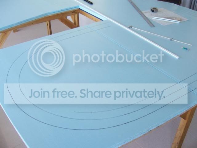
It is difficult to take pictures of this, I had to stand on a ladder with the camera almost touching the ceiling to get these.
It took me most of the afternoon to get this far, so I guess it will be a while before any actual track goes down!
Slow going but it sure is fun! I'm actually doing something on the layout! :Happy :Happy:Happy :Happy
Wayne
Posted
Full Member
Posted
Guest user
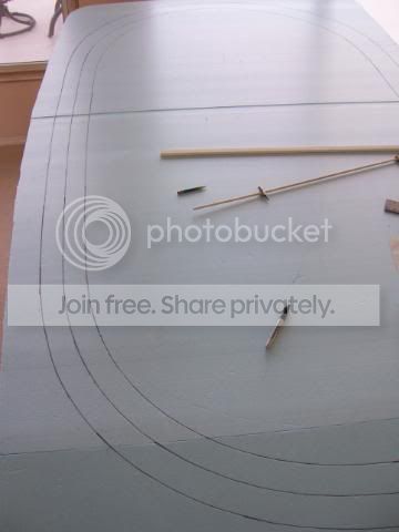
I've cheated this time, using set track curves (2nd and 3rd radius) to get my curves right, a i yard straightedge for the straights and turnout templates to draw in the branching lines. I still needed to resort to an old fashioned string line and pencil in places though :exclam:exclam
1 guest and 0 members have just viewed this.