Converting Bachmann's Jinty to EM
Posted
Inactive Member
...and upgrading too
Well done John,Another success.Have fun,
I have been knurling wheel axles with gusto.Had a few loose Gibsons now they are good and solid on the axles.
Derek.

Posted

Full Member
I dug out my Guy Williams' "4mm Engine" today. It was written in 1988 I think and it was interesting to see how things have changed. I note he uses a compensation system with elongated frame holes and brass tube bearings.
The Portescap motor/gearbox arrangement was the bees knees for a long time, but I think they are no longer available. I have a couple or three locos with these (second hand and needing considerable work to get them to EM) and I note that they are pretty whiny, unlike the whisper quiet mechanisms on RTR today. I may just leave the 00 chassis alone and make new ones.
John
John
Posted
Inactive Member
 .
.I guess marking the axle/wheel setting will be vital ?.
Oh well all part of the fun.
cheers,
Derek.
Posted
Full Member
John
John
Posted
Inactive Member
No expert myself when it comes to putting these things together.
On another note,Any special design needs for Kadee couplers and loco chassis building.Thinking ahead Don't want to build a chassis and find I cannot fit them.
Cheers,
Derek.
Posted
Full Member
I reviewed Tony Wright's DVD this morning to see how he does his pickups. Quite simple really and using his method got my pickups working. The loco works under it's own power which is good and feels fairly smooth. I'm still not happy though because every so often, the rear, driven, axle locks up. I'm thinking that the center bearings are oversize and that the coupling holes might also be oversize and too sloppy. So, back to the bench.
I'm almost ready to totally disassemble the chassis and reassemble using lessons I've learned - not quite yet though.
John
John
Posted
Full Member
I measured the wheels and flange depth comes out at ~1mm. I measured a couple of other, newer wheels, and the flange depth was ~0.5mm. Looks like I have some oldie wheels and will have to reduce the flanges. Not a big deal - just mount the wheel on an axle, put it into my Dremel and run the flange against a file. Concentricity doesn't matter. It is a durned nuisance because I have to remove the rods.
John
John
Posted
Inactive Member
C&L chairs are more pronounced than SMP. Sorry that the old wheelset started hopping on them.Seems its all finer scale these days,Noticed that things need to be a lot tighter on turnouts to avoid wheel dropping at least in 00.Or resort to packing the gap a little ?.OO BB gauges are another minefield.Anything between 14.5 to 14.83 depending on supplier and wheel profiles.
Cheers,
Derek.
Posted
Full Member
It's good that I discovered the discrepancy with flange depth now - easy to fix on this and other locos.
Yes, for 00, you do need to be careful. 00 coarse should be 14.5mm (for use with Peco points) and 00 fine should be 14.8mm. : http://www.doubleogauge.com/index.htm The "standards" is useful.
John
John
Posted

Full Member
As you have a lathe, this may be of interest for quatering
http://www.rmweb.co.uk/community/index.php?/blog/1672/entry-14896-snitzl-works-introduction-and-wheel-quartering-jigs/
or
Highly recommended in other forums
GW Models
(George Watts)
11 Croshaw Close
Lancing
West Sussex
BN15 9LE
tel: 01903 767 231
jigs, rolling bars, rivetting tool, wheel-quartering tool
Unfortunatly no web address.
Paul
Posted
Full Member
I had to actually write a letter requesting a quote incl postage and put in an actual mailbox. :shock: I got a reply a couple of weeks after that and then sent payment (bank money order). It all had a 50s feel to it.:roll: I only go through this rigmarole for things I really want and can't get any other way.
John
John
Posted
Inactive Member
Yes its odd these days useing a mail box and handwriting notes.
Cheers,
Derek.
Posted
Full Member
There's probably a lesson here: don't trust work that you did 2 years ago. I checked, or thought I did, the squareness a couple of days ago and it looked OK then, but that was before I changed the bearings. As I checked it again this morning, I noticed that the chassis isn't square :twisted:
So, right, I stripped it down to its' bare bones and started again.
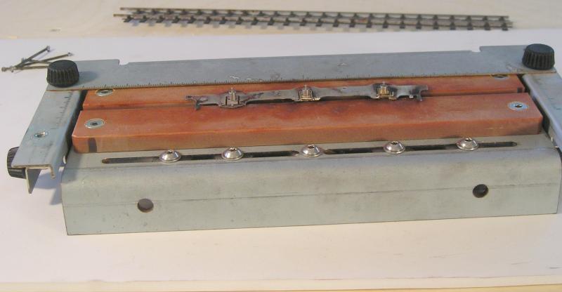
Now, a few years ago I convinced the family to get me an Avonside jig:
https://www.eileensemporium.com/index.php?page=shop.product_details&flypage=eny_fly_default.tpl&product_id=2342&category_id=127&option=com_virtuemart&Itemid=9
So, I thought I'd use that to make darn sure things are square this time.
First I filled the coupling holes with 188 solder and redrilled. These were reamed until they just fit on the jig pins.

These are the short pins. The pins are on stretchers that can be adjusted by knobs on the side. The pin spacing is set to the coupling rod holes. The screws on the edge are then tightened. Both sets of rods are checked. I found it necessary to touch the iron to the solder in a couple of the holes to center them on the pins.
I now have two sets of rods with identical hole spacings.
Next, I confirmed that the chassis bearings were correct:
Happily, these are OK. I checked both frames.
John
John
Posted
Full Member
Then place the other frame on the pins and solder the spacers in place:

Now, all being well, the chassis will be square. I'll find out when I get the wheels on.
John
John
Posted

Inactive Member
That jig is a beauty. :thumbs
Max
Port Elderley
Port Elderley
Posted
Inactive Member
Looks like an investment in 2015 is on the cards.
They are not cheap but quality never is.
regards,
Derek.
Posted
Full Member
Like this:

Thinking back, it's no wonder I had to make such large holes in the rods and why the chassis didn't seem happy with the gearbox installed.
John
John
Posted
Inactive Member
Still I bet you had fun all the same.
I was browsing Eileens metal stocks some usefull stuff there.2015 is going to be a busy year.
You mentioned a basement quite a rare thing in houses over here normally the loft for bigger layouts unless you are single and can let rip.
cheers,
Derek.
Posted
Full Member
I think it's worthwhile getting an understanding of the first principles.
Eileen's is a great place - some lovely kits from Bill Bedford too.
I am single
so I can do whatever the h*ll I want.John
John
Posted
Full Member
Yesterday, I painted the chassis and to day I installed brakes. I gave it another run to make sure I hadn't mucked anything up.
The wheels shouldn't need removing anymore so I used threadlocker Loctite to secure the wheel nuts - I find it impossible to torque them so they'll stay put.
I just glued some copper clad underneath for the wipers.
John
John
1 guest and 0 members have just viewed this.