Converting Bachmann's Jinty to EM
Posted
#166395
(In Topic #9498)

Full Member
...and upgrading too
To my mind, Bachmann's Jinty is one of the best of it's kind. It looks great and runs even better. It's perfect for shunting and out of the box will provide quite reliable slow running.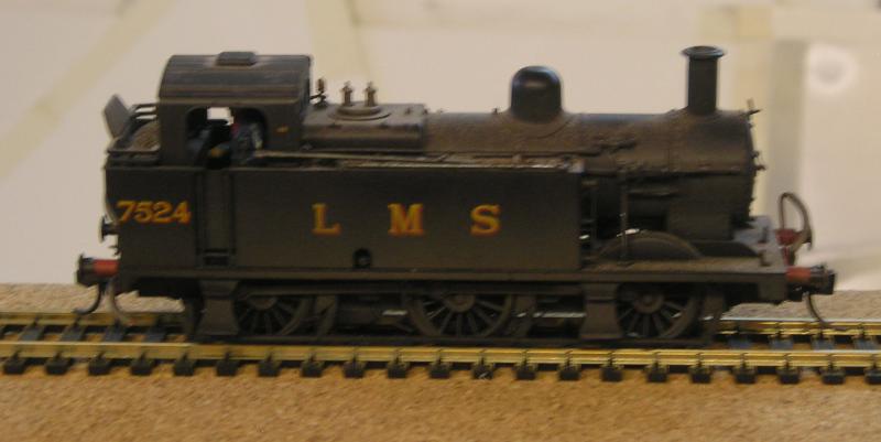
There's not a lot wrong with it, but because I am what I am, I will still find an excuse to make it even better. I've had Brassmaster's upgrade kit for quite a long time on my roundtoit shelf. I love their stuff, it's exquisite in execution and always well researched.
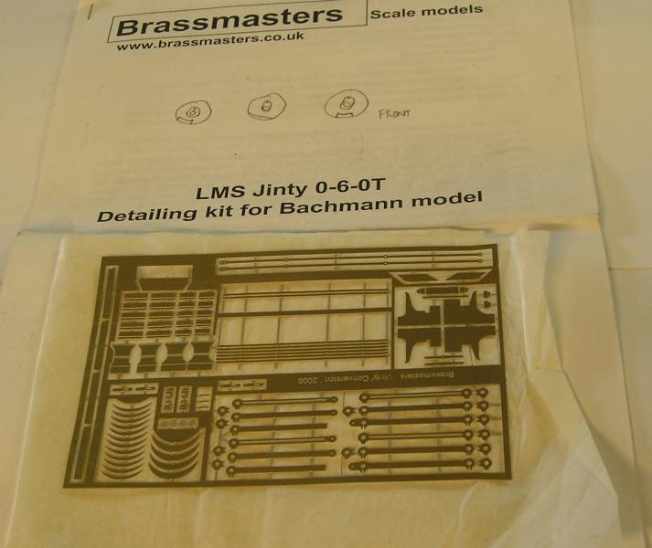
The kit also comes with a DVD containing dozens of pictures of the prototype and not just 3/4 views either, lots of lovely closeups. I'm not sure at this point just how much of the kit I will use. Another good source will be Tim Shackleton's article in MRJ 160 "Building a Better Jinty". This article goes into P4 conversion but, more useful to me, it also contains tips on improving the detail.
Now to grab MRJ 160 and have a read.
Oh and one other thing, I plan to utilise a Comet chassis kit. I will use the frames sandwiched with plastic card to increase the width of the chassis.
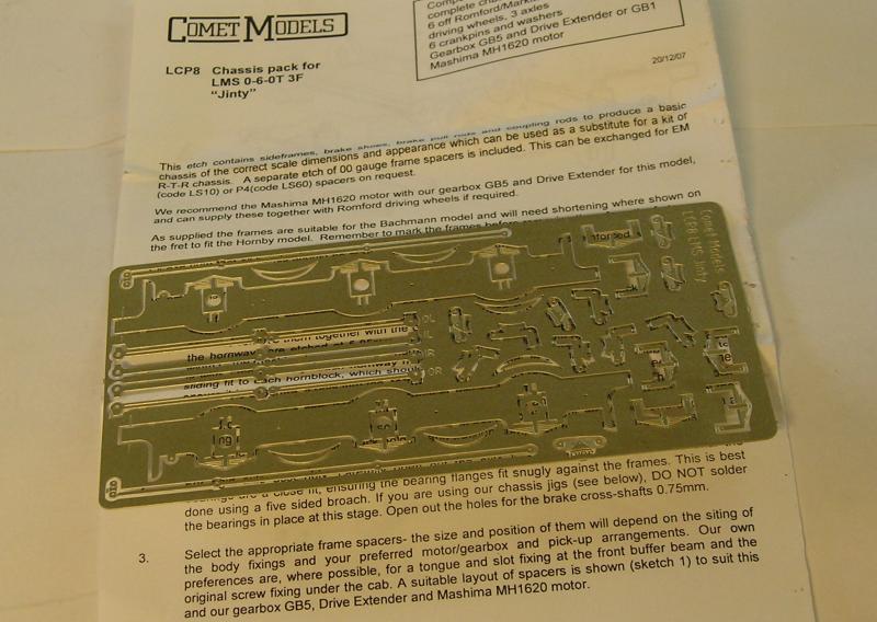
There is overlap between this and the Brassmaster's kit. Details haven't gelled in my head yet.
John
 Last edit: by Brossard
John

Posted
Inactive Member
Some of the P4 converter,s have also used lead sheet as a chassis sandwich. Both to add weight and as far as I know lead is an electrical non conducting material?
Of course plastic card maybe easier to work with.
Best of luck with this project.
My brother did not turn up today to do the lighting and power sockets in my workshop build.
So a little delayed on the lathe work for those Jinty axle spacer,s I plan on making.
regards,
Derek.
Posted
Full Member

Hmmm, I think lead does conduct, it's used in batteries. Finding lead in the small quantities I would need (and I'd like some for general ballast work) is difficult I think, since it's considered hazardous. TBH I haven't made much effort to look.
This morning I started the teardown and wheelwork.
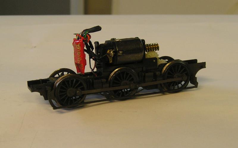
For completeness, the chassis. Note the hardwired decoder. This model is from an early batch before being DCC ready.

Wheels off. I used the wheel puller (right) and to my disgust the bushes stayed on the axle. I got these off using a gearpuller (left) and special adapter plate that I cobbled up.
My next job was to measure up and compare to Markits wheels.
Markits RTR
Width 2.44mm 2.72mm
Flange ~0.6mm ~0.7mm (EM calls for 0.54mm, this is critical)
Flange depth 1mm 0.9mm
For a control, I mounted a set of wheels on an EMGS axle as is. The wheels did go through the test point but I could feel that there was very little clearance at the crossing, which is the critical location.
Next I made a couple of gentle passes on the back of the wheel with a grinding attachment on my Dremel. I then rubbed the back of the wheel on a wide coarse file. This was then refined with a fine file, knocking off any sharp edges from the flange. I repeated the filing until I got a thickness of about 2.6mm. This gives me an effective flange of about 0.6mm.
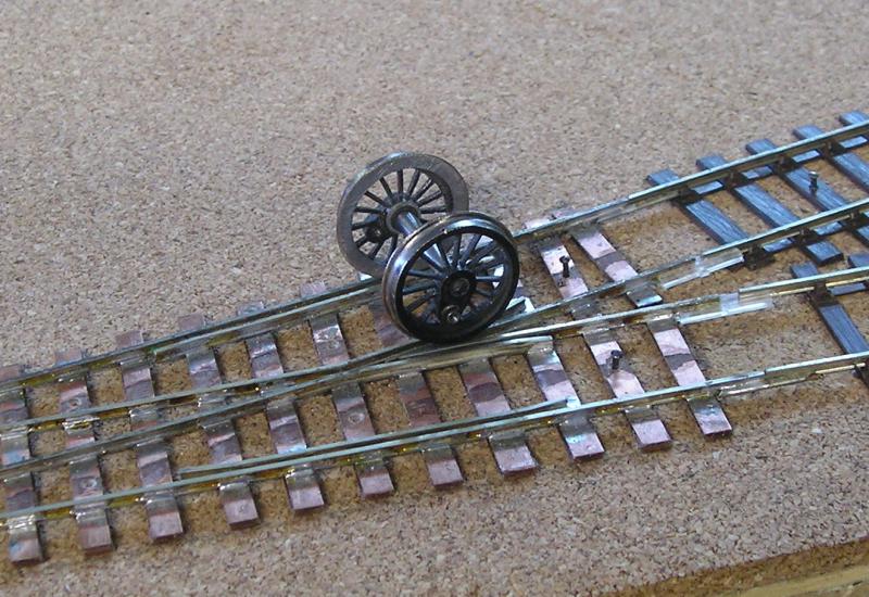
The picture shows the reworked wheels on the crossing. I can "feel" that there is good clearance now.
John
John
Posted
Inactive Member
Looking at those gear and wheel puller tools.
Reminds me of cycle chain breaker tools for pushing out the rivets on chain links, Hmmm?
Regarding getting lead.
Go to a builder,s hardware supplier and look for lead sheet roof flashing. I have a load from previous building jobs, It comes in rolls.
Or ask them if they have an odd spare length left over?
Of course old church roofs were a happy hunting ground for some people. Not suggesting that route of course.
regards,
Derek.
Posted
Full Member
Both my B2B gauges measure 16.3mm, should be 16.5mm so that's a bit of a nuisance.
John
John
Posted
Inactive Member
The plastic bush, Do you mean the flange of the bush on the inside of the wheel needs thinning?
After the Christmas break, I am going to order some 1/8th axle steel rod from Eileens Emporium, Plus some 3mm and turn some axles to the Bachman profile to suit EM gauge and the Bachman wheels. May save a lot of fiddling.?
regards,
Derek.
Posted
Full Member
Very enterprising of you to make your own axles, but you do know that EMGS axles aren't dear, ~ 1.00 each. Now making one's own axles for those locos designed with 2.14mm axles may be necessary - I haven't seen any EM ones. I have a piece of steel rod somewhere (if I could ever find it) that is just a bit larger than that.
John
John
Posted
Inactive Member
I am not a member of the EMGS.
I am a member of the Scale 4 society.
Typical Derek back to front.
If things turn out well with the axle,s ?
If I make a small batch of those 2.14mm ones you will be welcome to a set. I will use silver steel rod.
Oh Eileens Emporium do lead strip for model,s 1.3mm thick in various lengths and widths.
They are a great source for all sorts of things modeling.
regards,
Derek.
Posted
Full Member
I've used Eileen's in the past, very good indeed. I shudder to think what the postage will be for lead! Still, I did do a search and found that lead is still used for flashing, so I will have to check around.
Thanks for the offer on the axles, I'd better check to see what I've got with that size.
John
John
Posted

Full Member
The figures you quote give Markits wheels with a flange of 0.6mm and EMGS calls for 0.54mm. Does that extra 0.06mm on the wheels make all that difference to the clearance ?
If so, then you're working to much tighter tolerances than I thought ………… :shock::shock:
It was also interesting to see your DCC installation. I have a pre-DCC ready Jinty to chip at some time but following the trials and tribulations I had with a V2 (even though I was only following John Dew's tutorials), I'm a little reluctant to tackle it ………..:roll::roll::roll:
'Petermac
Posted
Full Member
eg, for 00 the latter sum is 14.5 + 2 x 0.7 = 15.9 vs a gauge of 16.5mm. For EM we get 16.5 + 2 x 0.6 = 17.7mm vs a gauge of 18.2mm.
I think Derek and myself are trying to understand the principles here which is why we're doing these experiments.
In the picture above, I think you can see that if the B2B is too small and/or the flanges too thick, the wheels will ride up on the checkrails. When having derail problems, the first thing to check is the wheel B2B, in my experience, resetting this usually corrects the hproblem.
I really like the engineering aspects of this but I suppose it can get a little tiresome.
John
Last edit: by Brossard
John
Posted
Full Member
The engineering aspect also interests me but my engineering was done with big hammers and not tweezers …………..:???:
'Petermac
Posted
Full Member
I've never actually read about or seen anyone do this before so I want to know whether it's feasible.
John
John
Posted
Full Member
Without looking at my Jinty, do these wheels have that "pick-up rim" for the pick-up wires to run against ? If so, are you going to replace it or just rely on the wheel itself for power ?
'Petermac
Posted
Full Member
Cheers
John
John
Posted

Full Member
Ultrascale do a conversion set of wheels including gears etc. The link below is to the PDF instructions, according to them you should be able to bend the pickups out far enough to reach the back of the wheel sets.
also suggests you may have additional work on the brakes.
Comet also do EM frame spacers - LS10
Peter - the DCC conversion for the Jinty is soooooo much easier than your V2. from memory - it is liable to muddle things
1. remove body
2. remove capacitors etc.
3. disconnect connections to motor - you may need to remove motor to make this easier
4. wire up the decoder
5. test it
6. refit body - if you cannot fit the decoder you can remove the weight in the boiler - I did this to place my stay alive capacitor
Go on you know you want to do it
Paul
Posted
Full Member
My preference for wheels for kits is Markits because they are robust and easy to quarter.
New Jintys come DCC ready. I have installed sound in my BR liveried Jinty (I just need to get rid of the lining that never existed in life).
This exercise is really an exploration of a few things that have been going around in my head, from RTR wheels to laminating Comet frames and plastic card to produce the chassis.
John
John
Posted
Full Member
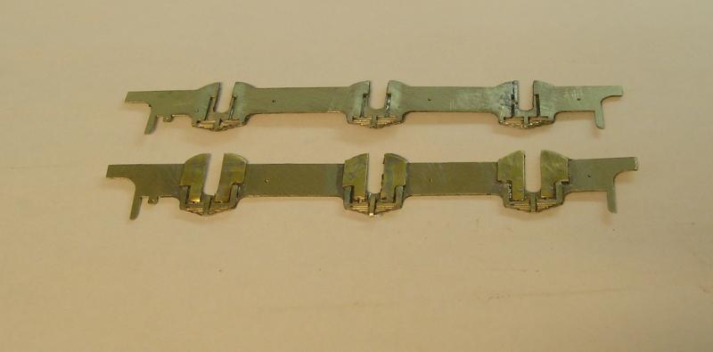
The idea is to attach the frames and brakes along with all the other gubbins to the keeper plate. This necessitates making slots so that everything can slide over the wheels. Not as easy as one might think since the frame would have been impossibly weak without the reinforcing plates - these took quite a long time.
I also made the springs double thickness for looks and strength.
John
John
Posted
Inactive Member
Neat job on those frames.
Tell me, How are you going to handle those sand boxes on the original chassis?
The loco will look superb if it all comes together.
regards,
Derek.
Posted
Full Member
I did some more frame prep today, soldering spacer pieces to the inside frames and putting pins in for the gluing to the keeper.
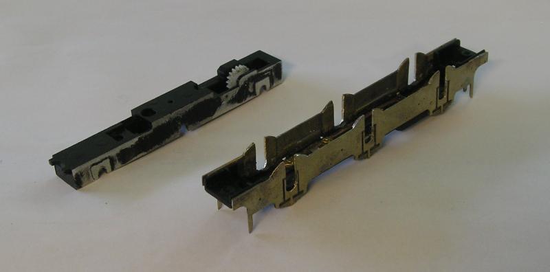
The two main chassis pieces.
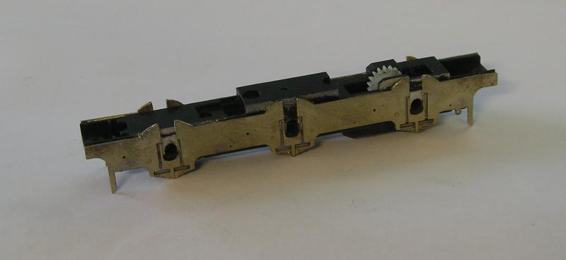
Upper chassis fits very snugly between the frames. They're something slightly over 13mm wide now. To my surprise the axle holes in the Bachmann chassis didn't quite match those in the frames so I had to do some additional filing.
I did a trial fit to the body and that's looking good too.
John
John
1 guest and 0 members have just viewed this.